background image

O

O

2

2

D

D

1

1

1

1

M

M


U

U

s

s

e

e

r

r

s

s


G

G

u

u

i

i

d

d

e

e


            Rev.1.4 (Oct. 2016) 

2


Caution 

Any  changes  or  modifications  in  construction  of  this  device  which  are  not  explicitly  approved  by  the 

party responsible for compliance could void the user’s warranty. 

Note 

This  equipment  has  been  tested  and  found  to  comply  with  the  limits  for  a  Class  A  digital  device, 

pursuant  to  part  15  of  the  FCC  Rules.  These  limits  are  designed  to  provide  reasonable  protection 

against  harmful  interference  in  a  residential  installation.  This  equipment  generate,  uses  and  can 

radiate radio frequency energy and, if not installed and used in accordance with the instructions, may 

cause harmful interference to radio communications. However, there is no guarantee that interference 

will not occur in a particular installation. If this equipment does cause harmful interference to radio or 

television  reception,  which  can  be  determined  by  turning  the  equipment  off  and  on,  the  user  is 

encouraged to try to correct the interference by one or more of the following measures:   


Reorient or relocate the receiving antenna. 


Increase the separation between the equipment and receiver. 


Connect the equipment into and outlet on a circuit different from that to which the receiver is 

connected 


Consult the dealer or an experienced radio/TV technician for help. 


Directions 

Be careful not to cause any physical damage by dropping or throwing the camera. Especially keep the 

device out of reach from children. 

Do not disassemble the camera. No after service is assumed when disassembled. 


Use only power adapters compatible with the unit. 

Be careful to prevent moisture or water penetration into the unit. Particular attention is needed when 

installing the unit. The screw holes for the installation screws and pipe should be maintained water tight 

during the whole life time of the product. 

All the electrical connection wires running into the unit should be prepared so that water from the outside 

cannot flow into the unit through the surface of the wires. Penetration of the moisture through the wire for 

extended period can cause malfunction of the unit or deteriorated image. 

Summary of Contents for O2D11M

Page 1: ...O2D11M 2MP 1080p H 265 Indoor Outdoor Dome IP Camera...

Page 2: ...y to correct the interference by one or more of the following measures Reorient or relocate the receiving antenna Increase the separation between the equipment and receiver Connect the equipment into...

Page 3: ...O O2 2D D1 11 1M M U Us se er r s s G Gu ui id de e Rev 1 4 Oct 2016 3 Revision History Date Revision Details Oct 26th 2016 1 4 First manual revision creation...

Page 4: ...y Default Switch 11 2 3 5 Camera Control SW3 SW4 12 2 4 Functional Description 12 3 On Site Installation 14 4 Getting Started 15 4 1 PC Requirement 15 4 2 Quick Installation Guide 15 4 2 1 Connect PC...

Page 5: ...ication is available through bidirectional audio communication feature H 265 is 40 50 reduction in bitrate at the same visual quality compared to H 264 Designed to be a stand alone streaming audio vid...

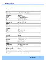
Page 6: ...Auto Flickerless On Off Shutter speed Max 1 30 000 White Balance AWB WDR On Off DNR 2DNR 3DNR Supported Day Night Auto ICR IR LED PRIVACY 1 Supported Anti fog Supported 5 Step Factory reset Supported...

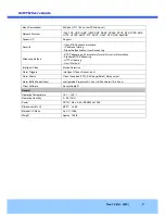
Page 7: ...ming method RTSP streaming with proprietary format for control informations Standard RTSP streaming HTTP streaming Onvif Profile S Intelligent Video Motion Detection Alarm Triggers Intelligent Video S...

Page 8: ...ity surveillance buildings stores manufacturing facilities parking lots banks government facilities military etc Remote monitoring hospitals kindergartens traffic public areas etc Teleconference Bi di...

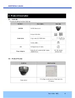
Page 9: ...Contents Description Remarks O2D11M O2D11M main unit Accessories Screws Anchors L type wrench CVBS Cable Guide pattern CD Software User s Guide Power Adaptor Default built in standard PoE module IEEE8...

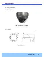
Page 10: ...O2 2D D1 11 1M M U Us se er r s s G Gu ui id de e Rev 1 4 Oct 2016 10 2 3 Physical description 2 3 1 External View Figure 2 1 External view of IP Camera 2 3 2 Dimensions Figure 2 2 Dimensions Unit inc...

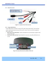
Page 11: ...dy cap of the camera There are two functions assigned to factory default switch 1 Returning to Factory Default State Press the switch about 5 seconds while power is applied to return to factory defaul...

Page 12: ...nto DC power connector Network LAN 100Mbps Ethernet connector RJ 45 with PoE standard 802 3af MIC Line Input Connect external audio source or microphone Micro SD Card slot Please insert SD memory card...

Page 13: ...2A Apply this connection when either voltage or current exceed the limit Figure 2 5 RELAY Output connection Sensor Input Connect external alarm sensor Examples of sensing devices are infrared sensor m...

Page 14: ...ture is allowed to penetrate into the unit through the cables or conduits during the life time of the product Products of which the internal parts are exposed to moisture because of improper installat...

Page 15: ...orer 8 or higher Graphic Card Video RAM 256MB Resolution 1920x1080 Video RAM 1GB Higher than 1920x1080 Network 10 Base T Ethernet 100 Base T Ethernet Operating Systems supported Windows 2000 Professio...

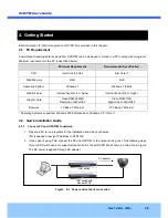
Page 16: ...e settings iv You can connect to admin page by clicking on 10 Click on the field in 3 for sorting and rearranging the list Select network mode that best suits from the drop down list in 5 You can choo...

Page 17: ...module should be installed on your PC before actual connection If your PC is not connected to the internet you cannot download Active X module Most convenient way of installing the Active X module is...

Page 18: ...sticated target application parameters need to be changed through the admin page The admin page can be connected through http IP_Address Port_Number admin htm ID and password of the administrator are...

Page 19: ...adaptor supplied by provider for the feeding of the power In case of replacing the DC power supply make sure that the power supply meets with the power requirement of the IP camera to prevent damage o...

Page 20: ...5 3 Technical Assistance If you need any technical assistance please contact technical support For immediate service please provide the following information 1 Model name 2 MAC address and Registrati...

Page 21: ...actory default button for 1 sec to unmount the SD Card SD Card can also be unmounted by going to Admin Page Sensor Capture Setup and clicking on CONFIRM button at the right of SD Card Unmount menu 2 U...

Reviews: