background image


iv 


Table of Contents  

1


Physical Specifications ......................................................................................................... 1


1.1


Device External Cable ...................................................................................................... 1


1.2


Dimensions ...................................................................................................................... 1


2


Device Installation ............................................................................................................... 3


3


IP Scanner ........................................................................................................................... 6


3.1


Overview ......................................................................................................................... 6


3.2


Operation ........................................................................................................................ 6


4


Web Operation .................................................................................................................... 7


4.1


Login and Main Interface ................................................................................................ 7


Summary of Contents for O3VFBM

Page 1: ...Quick Start Guide 3MP VF Motorized Bullet IP Camera O3VFBM Version 1 0 1 ...

Page 2: ...is owner s manual is designed to be a reference tool for your system Please read this manual carefully before operating the unit and retain it for future reference Should you require any technical assistance please contact Speco Technologies Technical Support ...

Page 3: ...mperature conditions Do not expose the camera to electromagnetic radiation Otherwise it may result in CMOS sensor failure Do not block any ventilation openings Do not allow water and liquid intrusion into the camera 3 Operation and Daily Maintenance Please shut down the device and then unplug the power cable before you begin any maintenance work Do not touch the CMOS sensor optic component You can...

Page 4: ... without prior notice Speco Technologies reserves the right to modify these without notice and without incurring any obligation Speco Technologies is not liable for any loss caused by improper operation Note Before installation check the package and make sure that all components are included Contact your rep or Speco customer service department immediately if something is broken or missing in the ...

Page 5: ...ble of Contents 1 Physical Specifications 1 1 1 Device External Cable 1 1 2 Dimensions 1 2 Device Installation 3 3 IP Scanner 6 3 1 Overview 6 3 2 Operation 6 4 Web Operation 7 4 1 Login and Main Interface 7 ...

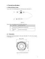
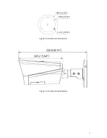
Page 6: ...1 Please refer to the following sheet for detailed information No Port name Function description 1 Ethernet port Network data in out and PoE 2 DC power jack Connect to DC 12V power 1 2 Dimensions Please refer to the following figure for dimension information The unit is mm See Figure 1 2 and Figure 1 4 Figure 1 2 Dimension illustration 1 ...

Page 7: ...2 Figure 1 2 Dimension illustration 2 Figure 1 3 Dimension illustration 3 ...

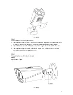
Page 8: ... a minimum of 3 times the weight of the camera Figure 2 1 Step 1 Install Micro SD card Open the lower cover find the Micro SD card slot as shown in Figure 2 2 insert it into the slot and make sure it is firmly latched in the slot Install the lower cover back to the device after installation is completed ...

Page 9: ...rill holes according to the hole locations marked on the template 2 Take out the expansion bolts from the accessories bag and insert them into the holes 3 Take out the installation screws Tighten the screws to fix the device on the surface Adjust the sunshield and tighten the screw Step 3 Plug external wiring of the device properly Step 4 Adjust device angle Figure 2 3 ...

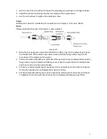
Page 10: ...t keep the smaller hole of the rubber ring outward and install the fixing rubber ring into the main body of the waterproof connector 2 Pull the network cable without crystal head through main body of waterproof connector fixing rubber ring and waterproof locking cover make the crystal head of network cable and then insert it into the network cable 3 Put the main body of waterproof connector on the...

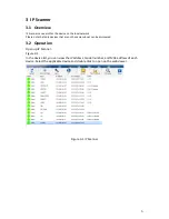
Page 11: ...ote that only devices that are on the same subnet can be discovered 3 2 Operation Open up IP Scanner Figure 3 1 In the device list you can view the IP address model number and MAC address of each device Select the applicable device and double click to open up the web viewer Figure 3 1 IP Scanner ...

Page 12: ...ess in the address bar or double click the device in IP Scanner See Figure 4 1 Figure 4 1 IP address The login interface is shown as below See Figure 4 2 Please input your user name and password Default user name is admin and password is 1234 Note For security purposes please change the password after initial login Figure 4 2 Web login Input your IP address here ...

Reviews: