background image

5

KolibriSensor

V2.0 | June 17, 2014

Chapter 3 – Operation

The Starter Kit allows the characterization of a KolibriSensor in a simple setup separate from a

microscope. You can easily vary the conditions of the setup as part of your investigations. This

chapter covers the following topics for basic operation:

Ÿ

Installing a KolibriSensor into receptor of the test stage.

Ÿ

Finding the oscillation parameters of the KolibriSensor.

Ÿ

Removing the KolibriSensor from the test stage.

3.1

Inserting a KolibriSensor into the Test Stage

The KolibriSensor is stored in a transport package when it is not in use. SPECS supplies a spe-

cial pair of tweezers for handling the KolibriSensor. These are shaped so that they will correctly

grip the KolibriSensor: this greatly simplifies the process of inserting and removing the sensor.

Caution!

Only use the special tweezers when handling the KolibriSensor in order to avoid

damaging the sensor tip.

To insert the KolibriSensor into the test stage:
1. Remove the transport hood from the test stage by loosening the two screws that hold it.
2. Ensure that no excitation signal is applied to the test stage.
3. Open the sensor package.
4. Use the special tweezers to grip the sensor below the guidance ring (highlighted in red in

Figure 3) and gently pull the sensor out of the spring holder in the sensor packaging.

Figure 3: Removing the KolibriSensor from the holder

5. Put the sensor on a clean table so that it rests on its ceramic base.

Summary of Contents for KolibriSensor

Page 1: ...KolibriSensor Starter Kit User Manual V2 0 June 17 2014...

Page 2: ...2 0 June 17 2014 SPECS order number reference 78000248 2014 All rights reserved No part of this manual may be reproduced without the prior per mission of SPECS GmbH Kolibri and KolibriSensor are regis...

Page 3: ...ng Conditions 1 Chapter 2 Installation 2 1 Unpacking 3 2 2 Electrical Connections 4 Chapter 3 Operation 3 1 Inserting a KolibriSensor into the Test Stage 5 3 2 Setting Up Oscillation Parameters 6 3 3...

Page 4: ...This page intentionally left blank KolibriSensor V2 0 June 17 2014 iv...

Page 5: ...nsor ready for insertion into the receptor 6 Figure 5 Aligning the sensor into the receptor 6 Figure 6 Settings in the Oscillation Control panel 7 Figure 7 Signals in Frequency Sweep panel 8 Figure 8...

Page 6: ...This page intentionally left blank KolibriSensor V2 0 June 17 2014 vi...

Page 7: ...s please refer to Nanonis software Online Help press F1 for context sensitive help of the currently open panel SPECS SPM 150 manual For further advice and assistance please also contact SPECS support...

Page 8: ...s 40 80 recommended range 50 60 There must be no condensed water on the equipment Atmospheric pressure 800 1200 mbar Air conditioning is advisable in order to ensure the ambient requirements especiall...

Page 9: ...eration 2 1 Unpacking A packing list is provided with the delivery of the Starter Kit Please check that all items are present and that none of the equipment is damaged In case of missing or damaged pa...

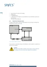
Page 10: ...stage All connectors are labeled on the instruments and cables EXCITATION Attenuator Output Input Out Usupply OSCILLATION It 15 V In Test stage KolibriPreamp Nanonis Oscillation Controller Attenuator...

Page 11: ...tweezers for handling the KolibriSensor These are shaped so that they will correctly grip the KolibriSensor this greatly simplifies the process of inserting and removing the sensor Caution Only use t...

Page 12: ...Push the sensor gently into the receptor The sensor will slide into the correct position The sensor is now in place and ready for measurements 9 Fit the transport hood back onto the test stage This p...

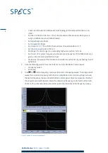
Page 13: ...isplays a tooltip explain ing the function of the control To set up the oscillation parameters 1 Switch on both the Nanonis Realtime Controller and Oscillation Controller 2 Start the Nanonis SPM Contr...

Page 14: ...olibriSensor as given on the sensor s specification sheet Make sure the output of the Oscillation Controller is switched on by unchecking the off option box 5 Open the following panels from the Tools...

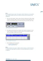
Page 15: ...ures that you have found the correct value Figure 8 Altering the sweep range or number of points 8 Press Apply next to the row of values in the table in the Frequency Sweep panel This will transfer th...

Page 16: ...the sensor oscil lation at the resonance frequency with controlled oscillation amplitude 3 3 Removing a KolibriSensor from the Test Stage To remove the KolibriSensor from the test stage 1 Remove the...

Page 17: ...of a vacuum chamber As a result it is easy to integrate into an experimental setup It eliminates the need for complicated expensive and potentially unreliable in situ preamplifiers The KolibriPreamp s...

Page 18: ...onnected in series between the output of the Nanonis Oscillation Controller and the Excitation input of the test stage The attenuators protect the KolibriSensor from excessive drive levels and improve...

Reviews: