KolibriSensor
V2.0 | June 17, 2014
Check the
diff
option for differential input topology of the Nanonis Oscillation Con-
troller.
Set the
Cal.
field to 1.43 nm/V. This is the standard calibration value when you are
using a KolibriSensor and a KolibriPreamp.
Set
Input Range
to 400 pm.
Set
Setpoint
to 300 pm
Set
Output
to 0.1. This will limit the maximum drive amplitude to 0.1 V.
Set the
Drive Amplitude
to 100 mV.
Set
Range
(PLL lock range) to a reasonably high value such as 1.22 kHz.
Set
fcenter
(PLL center frequency) to the resonance frequency of the KolibriSensor as
given on the sensor’s specification sheet.
Make sure the output of the Oscillation Controller is switched on by unchecking the
off
option box.
5. Open the following panels from the
Tools
menu in the Oscillation Control panel:
Frequency Sweep
PLL Setup
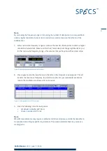
6. Click
or
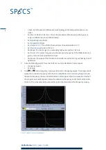
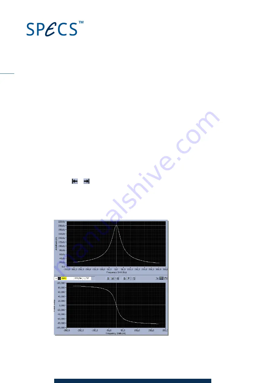
in the Frequency Sweep panel to start a frequency sweep. The program will
sweep the excitation frequency with the
Drive Amplitude
in the
Frequency Range
around
the center frequency chosen in the Oscillation Control panel. After the sweep has finished
the program automatically determines the resonance frequency and Q factor of the Kolib-
riSensor. The screenshot below shows the typical characteristic of the frequency sweep.
Figure 7: Signals in Frequency Sweep panel
8


