KolibriSensor
V2.0 | June 17, 2014
Special tweezers for safe sensor handling.
KolibriPreamp
2× 20 dB attenuators.
3× KolibriSensors with tungsten tip. Each KolibriSensor is provided with a separate spe-
cification sheet.
Test stage with KolibriReceptor.
2.2
Electrical Connections
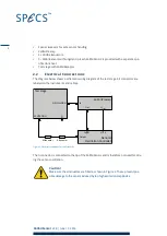
The diagram below shows a schematic wiring diagram of the test stage. All connectors are
labeled on the instruments and cables.
EXCITATION
Attenuator
Output
Input
Out
U
supply
OSCILLATION
I
t
±15 V
In
Test stage
KolibriPreamp
Nanonis
Oscillation Controller
Attenuator
Figure 2: Electrical connections for the Starter Kit
The I
t
connector is connected to the tip of the KolibriSensor and is therefore not used for driv-
ing the sensor oscillation.
Caution!
Make sure the attenuators are fitted as shown in Figure 2. These prevent pos-
sible damage to the sensor induced by too high excitation amplitudes.
4


