KolibriSensor
V2.0 | June 17, 2014
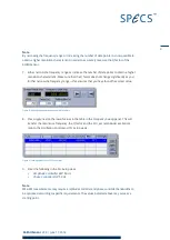
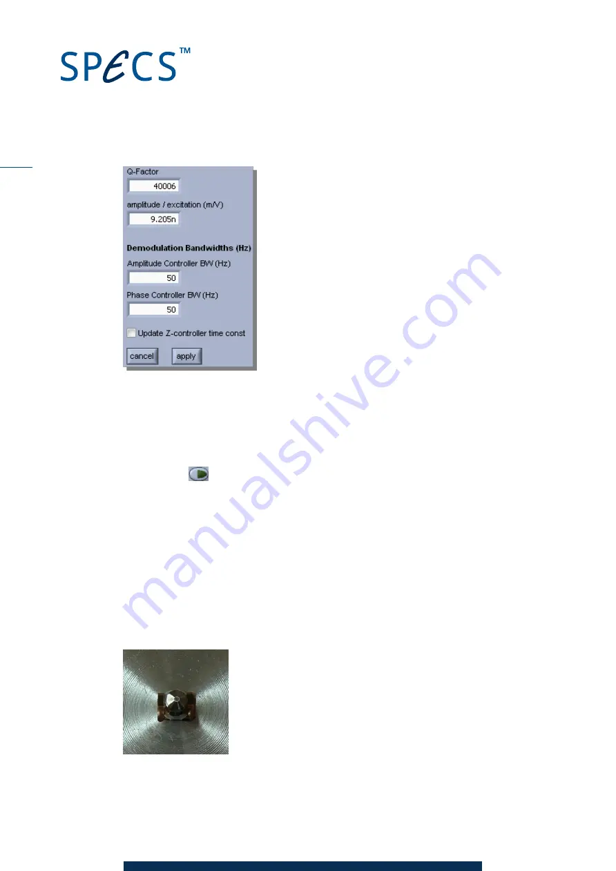
Figure 10: PLL Setup view
10. Click
Apply
to set the values in the PLL Setup view. The perfectPLL algorithm will auto-
matically set the amplitude and phase controller parameters according to the sensor para-
meters and selected controller bandwidths.
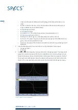
11. Switch on Amplitude and Phase control in the Oscillation Control view by pressing the
respective
buttons. The Nanonis Oscillation Controller will now drive the sensor oscil-
lation at the resonance frequency with controlled oscillation amplitude.
3.3
Removing a KolibriSensor from the Test Stage
To remove the KolibriSensor from the test stage:
1. Remove the sensor by gripping it below the guidance ring with the tweezers and pulling it
out of the KolibriReceptor.
2. Put the sensor back into the sensor package. Ensure that the sensor is firmly held in place
by the spring holder—some orientations of the base plate with respect to the springs may
result in a rather weak spring force. See the photograph below for the correct orientation
of the sensor in the holder.
Figure 11: Sensor packaging
10

