SC5 Signal Conversion
Installation Guide
•
18
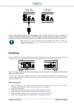
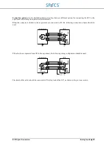
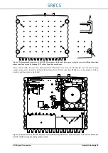
Figure 6: Electrical GND options for the SC5 depending on the
instrument. Left: BNC short plug connected, AGND and therefore the shields of the analog outputs
connected to PE. Right: No BNC short plug connected, AGND and PE are separated by two 10 k
Ω
resistors in parallel.
Note:
should not be used for applying offset voltages to AGND. The
maximum potential difference between AGND and PE should never exceed 5 V, or the power supply
of the SC5 will be damaged.
Powering
Make sure that the SC5 is connected to the Nanonis RC5 as described in the previous section. Turn on the SC5 with
(4) located at the back of the unit (see picture below). The
Figure 7: Powering of the SC5. Left side: Location of the power switch at the back of the SC5. Right side: LED which will
turn on after powering the unit.
The SC5 is now ready for use. Should the SC5 not turn on as described above, please refer to the
section before proceeding. If a solution to the unexpected behavior is not listed there, please contact SPECS before
taking any further action.
How to proceed
•
Make sure that the SC5 is connected to the Nanonis RC5 as explained in the
Otherwise switch off the SC5, connect it to the RC5, then switch it on again.
•
Turn on the Nanonis RC5
•
Start the Nanonis software and make sure that all output voltages are set to 0 V
•
Connect the analog inputs of the SC5 as described in the
•
Connect the analog outputs of the SC5 as described in the
•
Connect the fast analog output as described in the
AGND and PE
connected at SC5
AGND and PE
disconnected
Summary of Contents for Nanonis SC5
Page 1: ...Signal Conversion SC5 User Manual November 2016 R6860...
Page 2: ......
Page 5: ...SC5 Signal Conversion Conventions 5...
Page 8: ......
Page 72: ......
Page 74: ......
Page 75: ...SC5 Signal Conversion Legal Information 75 Declaration of Conformity...

