SC5 Signal Conversion
Analog Inputs
•
23
Analog inputs schematic
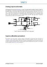
The input stage of each of the 8
(1) consists of an instrumentation amplifier frontend, the inputs are
thus differential. The frontend is preceded by a digitally controlled switch, which selects the input signal to be
measured. During normal operation the input BNC connector signal is used. During calibration, the switch can select
AGND, the reference voltage for the ADC, or the signal of the corresponding analog output (AO1 to AI1, AO2 to
AI2, …, AO8 to AI8). The schematic in the figure below shows the input stage of one of the eight analog inputs.
After the input stage, the signal passes a 5
th
order (Butterworth) active low-pass filter with a corner frequency of 100
kHz (-3 dB), before being digitized at a rate of 1 MS/s with an 18-bit ADC. Each input channel is completely
independent from the others, and no multiplexing is used.
Figure 9: Schematic of the input stage of the SC5 analog inputs.
Inputs calibration procedure
The calibration of the analog inputs is performed together with the hrDAC™ calibration described in the hrDAC™
section. The calibration procedure runs fully automatically, and does not require the
instrument to be disconnected from the experiment. Note that the actual calibration will start only after the SC5 has
reached its operating temperature, which is about four hours after the instrument has been powered on. For details,
please consult the
Input selector
Summary of Contents for Nanonis SC5
Page 1: ...Signal Conversion SC5 User Manual November 2016 R6860...
Page 2: ......
Page 5: ...SC5 Signal Conversion Conventions 5...
Page 8: ......
Page 72: ......
Page 74: ......
Page 75: ...SC5 Signal Conversion Legal Information 75 Declaration of Conformity...

