SC5 Signal Conversion
Analog Outputs
•
26
Specific connection options
Connection using shielded twisted-pair cables:
The same arguments concerning the use of coaxial cables as
discussed for the analog inputs (see the
section for details) also apply to the analog
outputs.
Depending on the signal input at the experiment, also in this case, the shortcomings inherent to the use of coaxial
cables can be reduced by preparing shielded twisted-pair cables according to the general rules discussed below.
These are suggestions; improvements will depend on the measurement set-up, and have to be determined
experimentally.
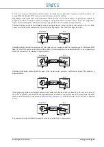
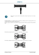
Shielded twisted-pair cables should not be used if the signal input is single-ended and referenced to PE, or a BNC
connector with the shield connected to PE is used at the experiment. Note that in this case AGND and PE will be
connected together at the experiment. The situation is depicted below:
Shielded twisted-pair cables can be used when the signal input is single-ended, but the device the voltage is applied
to is referenced to a GND connected to the shield of the experiment input BNC as shown below. The GND can be
either a larger part of the experiment, or just the return path for the applied signal.
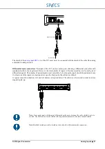
Shielded twisted pair cables should be used if there is a differential buffer after the input connector at the experiment
as shown below. This solution can lead to best results, but only if the specifications of the buffer and its associated
circuitry are at the same level as those of the analog outputs of the SC5, and if the buffer provides sufficient CMRR.
The input impedance of the buffer should not be below 1 k
Ω
.
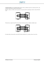
Differential mode connection:
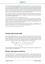
The outputs of the SC5 can be easily paired, thereby increasing the (differential)
voltage range to ±20 V, and allowing a differential connection to the experiment. However, the total number of
outputs is then decreased by one for each pair of differential signals. The number of paired outputs is user selectable,
but only nearby outputs should be paired, and only if at least one of the outputs is not assigned to a specific function
by the software as default. A differential pair of outputs is defined in the software by setting the negative output as a
“Monitor” channel of the positive output, with a negative (-1) calibration.
A typical connection situation (AO1 and AO2 shown) is depicted below. The cables can be twisted in order to
reduce magnetic pick-up:
Experiment
SC5
PE
AGND
PE
SC5
AGND
PE
Experiment
PE
To rear
panel
SC5
AGND
PE
Experiment
PE
To rear
panel
Meas. GND
Summary of Contents for Nanonis SC5
Page 1: ...Signal Conversion SC5 User Manual November 2016 R6860...
Page 2: ......
Page 5: ...SC5 Signal Conversion Conventions 5...
Page 8: ......
Page 72: ......
Page 74: ......
Page 75: ...SC5 Signal Conversion Legal Information 75 Declaration of Conformity...

