SC5 Signal Conversion
Performance Measurements
•
50
Input voltage 12 h
T-induced drift
drift
Max. internal
Δ
T
0 V
< 80 µV
0.3 °C
≅
0.8 µV
9.9 V
< 100 µV 0.3 °C
≅
35 µV
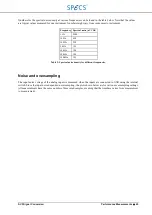
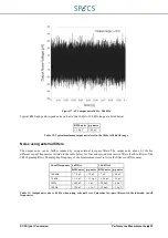
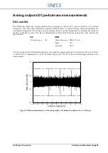
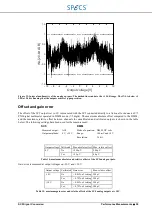
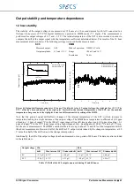
Table 7: Drift of the SC5 inputs measured during 12 and 48 hours.
Temperature coefficient
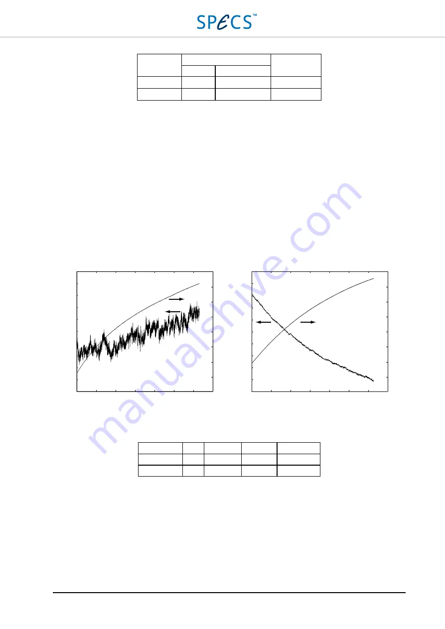
The temperature coefficient is determined by changing the environment temperature and recording both the input
voltage (AI1) and the internal temperature of the SC5. The measurement is done for 0 V (input shorted) and 9.9 V
input voltage, with the 9.9 V applied from AO1. In that case, the temperature coefficient from the analog output also
influences the measurement. The temperature coefficient is determined after removing the temperature influence of
the output. For negative voltages the temperature coefficient is positive, while for positive voltages it is negative.
Note:
The temperature coefficient is determined with respect to the internal temperature of the instrument. The
internal temperature varies considerably less than the external temperature, meaning that the temperature coefficient
is smaller when based on the environment temperature.
Note:
During normal operation, the SC5 reaches a typical operating temperature of 38 – 42 °C. The temperature
coefficient around the operating temperature is lower than the worst-case value given below.
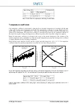
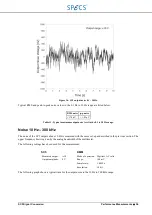
Figure 28: Temperature dependence of the input voltage on the internal temperature of the SC5. The left plot is for 0 V
input voltage, the right plot for +9.9 V. The contribution of the analog output has not been subtracted in the plot.
Input voltage
Δ
T
Δ
V
max
V
out
contr. Tc
max
0 V
30 °C < 80 µV
< 2.7 µV/°C
9.9 V
28 °C < -1.45 mV +1.99 mV < -115 µV/°C
Table 8: Temperature coefficient of the analog inputs, after subtracting the analog output contribution for the 9.9 V
measurement.
0
5
10
15
20
25
30
35
0
5
10
15
20
25
30
35
Time [min]
In
pu
tv
ol
ta
ge
[
μ
V
]
In
te
rn
al
te
m
pe
ra
tu
re
[°
C
]
-300
-320
-340
-360
-380
-400
-420
-440
-460
-480
-500
45
40
35
30
25
20
15
10
5
45
40
35
30
25
20
15
10
5
In
te
rn
al
te
m
pe
ra
tu
re
[°
C
]
Time [min]
O
ut
pu
tv
ol
ta
ge
[m
V
-9
.9
V
]
6.6
6.4
6.2
6.0
5.8
5.6
5.4
5.2
5.0
4.8
4.6
Input range: ±10 V
Input voltage: +9.9 V
Input range: ±10 V
Input voltage: 0 V
Summary of Contents for Nanonis SC5
Page 1: ...Signal Conversion SC5 User Manual November 2016 R6860...
Page 2: ......
Page 5: ...SC5 Signal Conversion Conventions 5...
Page 8: ......
Page 72: ......
Page 74: ......
Page 75: ...SC5 Signal Conversion Legal Information 75 Declaration of Conformity...


