SC5 Signal Conversion
Instrument Overview
•
13
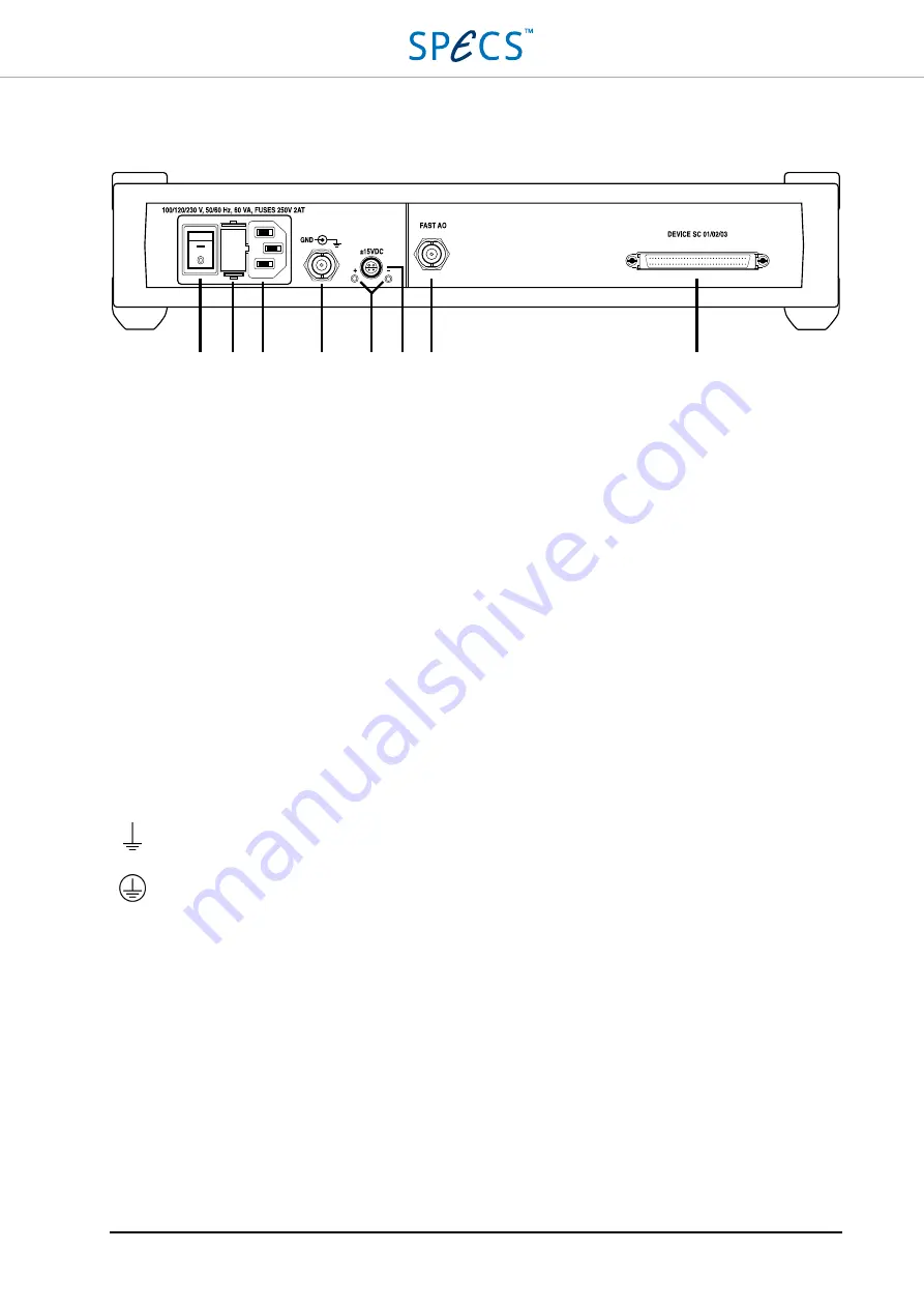
Rear panel
Figure 3: SC5 rear panel.
4.
Power switch:
Turns the SC5 on and off.
5.
Fuse holder:
Contains two identical slow blowing fuses, each one connected to line and neutral of the power
supply transformer. Slow blowing 2A fuses (2AT, rated 250 VAC, 5×20 mm) should be used regardless of the
line voltage.
6.
IEC power socket.
7.
GND BNC connector:
The shield of this connector is connected to protection earth (PE), and therefore also to
the SC5 chassis. The inner conductor is connected to the GND reference of the analog electronics (AGND). See
8.
Status LEDs (green):
Indicate that the positive and negative rails of the auxiliary power supply are providing
the correct voltages (+15 V and -15 V respectively), and are not overloaded. If the external device connected to
the
auxiliary power supply connector
(9) is drawing too much current (more than 300 mA per rail), the LED of
the overloaded rail will start flashing with a frequency of 5-10 Hz. See the
details.
9.
Auxiliary power supply connector:
This connector supplies ±15 V with a maximum current of 300 mA per
rail. It can be used to power external devices like preamplifiers. See the
details.
10.
FAST AO:
This BNC plug provides an additional analog output with a bandwidth of 1 MHz (-3dB). It can
deliver voltages up to ±10 V and currents up to ±20 mA. The shield of the BNC connector is connected to
AGND. For more details, please refer to the
11.
DEVICE SC 01/02/03:
This connector is used for the communication between the SC5 and the
Nanonis RC5
.
The cable for the connection between the two instruments is provided with the SC5.
Symbols:
Earth
Protection Earth
GND
Analog Ground
4 5 6 7 8 9 10
11
Summary of Contents for Nanonis SC5
Page 1: ...Signal Conversion SC5 User Manual November 2016 R6860...
Page 2: ......
Page 5: ...SC5 Signal Conversion Conventions 5...
Page 8: ......
Page 72: ......
Page 74: ......
Page 75: ...SC5 Signal Conversion Legal Information 75 Declaration of Conformity...


