SC5 Signal Conversion
Installation Guide
•
17
Note:
If two SC5s are connected to the RC5, they must be connected to the SC 01 and SC 02 ports at
the back of the RC5. Do not connect the second SC5 to the SC 03 port.
Note:
The SC5 must be able to dissipate a large amount of heat. It is not recommended to stack three
SC5s on top of the RC5 unless an external source of forced cooling provides a stream of air towards
the SC5 enclosures. It is recommended to use a mixed arrangement with SC5s placed below and above
the RC5.
Caution:
Avoid touching the instrument and the BNC connectors if multiple SC5s are stacked on top
of each other since the surface of the instruments and the connectors may become very hot. Switch off
the instrument and let it cool down before touching it.
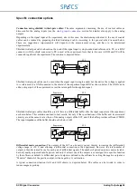
Electrical ground
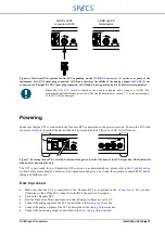
The SC5 allows for different configurations of the electrical ground. The enclosure of the SC5 is connected to the
protection earth (PE) provided by the AC power line. The ground reference for the analog electronics (AGND) is not
directly connected to PE, but separated by two 10 k
Ω
resistors in parallel. If necessary, AGND can be shorted to PE
by connecting a BNC short plug to the
(7) on the rear panel. By shorting AGND and PE, all
shields of the analog output connectors
(2) are also connected to PE. Note that all analog outputs are
referenced to the same electrical ground (AGND) and are not floated with respect to each other.
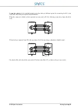
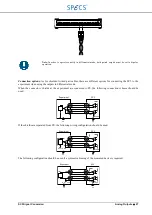
If the experimental setup requires AGND and PE to not be connected together, the
GND BNC connector
(7) on the
rear panel of the SC5 should be left open. AGND and PE are then separated by two 10 k
Ω
resistors in parallel. In
this case a GND reference for the SC5 electronics must be provided from the experiment over the shield of the
coaxial cables connected between
AO1-AO8
(2) and the experiment. The maximum voltage difference between
AGND and PE should never exceed 5 V. The two configurations for the
GND BNC connector
(7) are shown in the
picture below.
Note that the analog inputs are differential, therefore the shield of the analog input connectors
connected neither to AGND nor to PE. It is not possible to provide a GND reference for the SC5 analog electronics
over the shield of coaxial cables connected to the analog inputs.
The reference ground of the digital electronics (DGND) and AGND are connected together only at the GND star
point. The reference GND of the
is separated from AGND by a 100
Ω resistor. This resistor
cannot be bridged.
The digital GND of the RC5 is completely separated from the GND of the SC5. It is connected to PE of the RC5 by
a 1 k
Ω resistor, but PE of the two instruments is connected together only over the power cord, no
The best electrical ground setup depends on the characteristics of the experimental setup, and has to be determined
experimentally. However, a good starting point is to keep the BNC short plug connected at the back of the SC5.
Summary of Contents for Nanonis SC5
Page 1: ...Signal Conversion SC5 User Manual November 2016 R6860...
Page 2: ......
Page 5: ...SC5 Signal Conversion Conventions 5...
Page 8: ......
Page 72: ......
Page 74: ......
Page 75: ...SC5 Signal Conversion Legal Information 75 Declaration of Conformity...


