SC5 Signal Conversion
Analog Inputs
•
19
Analog Inputs
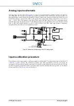
This chapter explains how to connect the SC5 analog inputs
(1) to other equipment, and explains in more
detail the input stages of the instrument.
Analog inputs connection
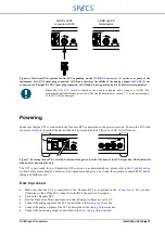
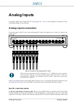
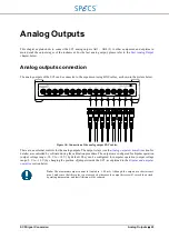
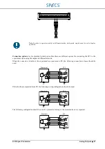
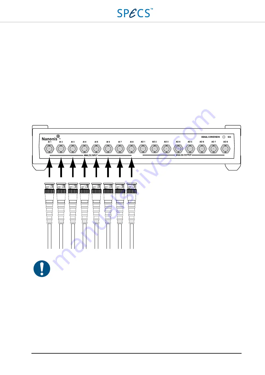
The analog inputs of the SC5 can be connected using BNC cables to the signal source of interest, as shown in the
picture below.
Figure 8: Connection of the analog input BNC cables.
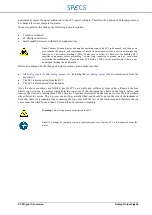
Note:
The input voltage range of the SC5 analog inputs is ±10 V. Although the inputs are protected
against electrostatic discharge, the absolute maximum applied voltage with respect to AGND must
never exceed ±13 V or damage to the instrument will occur. The limit is valid for both center pin and
shield of the BNC connectors.
There are no external controls for the analog inputs. The gain is set to 1 for all inputs, and input signal selection (see
section for details) is controlled by software during the calibration procedure.
Specific connection options
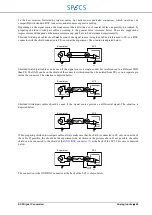
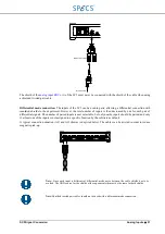
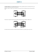
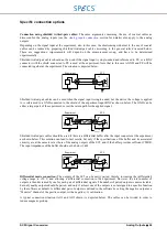
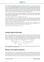
Connection using shielded twisted-pair cables:
The use of coaxial BNC cables as a standard connection is dictated
by their widespread use and general availability in research laboratories. Coaxial cables are, however, not the ideal
solution for low-frequency signals in the frequency range that the SC5 operates. Shielded twisted-pair cables would
Summary of Contents for Nanonis SC5
Page 1: ...Signal Conversion SC5 User Manual November 2016 R6860...
Page 2: ......
Page 5: ...SC5 Signal Conversion Conventions 5...
Page 8: ......
Page 72: ......
Page 74: ......
Page 75: ...SC5 Signal Conversion Legal Information 75 Declaration of Conformity...


