SC5 Signal Conversion
Analog Outputs
•
28
Use of external attenuators and low-pass filters
: The analog outputs of the SC5 have a fixed voltage range of ± 10
V (or 0 to 10 V in unipolar operation), and the corner frequency of the output low-pass filters cannot be changed
from its 40 kHz (-3 dB) setting. Although the output noise of the SC5 is very low, additional reduction of the noise
using attenuation might be desired. However, in most cases, the experiment is placed at a considerable distance from
the SC5 (up to 10 m). Over such distances, the signal will be prone to common-mode noise pick-up, and to other
effects due to the long cabling (e.g. triboelectric effects), which will become more significant with a smaller signal
amplitude. Therefore, attenuators should be placed as close to the experiment as possible, allowing large amplitudes
to be carried over the long distance, and also allowing attenuation of external interference.
If passive attenuators (voltage dividers) are used, the total resistance to AGND (both divider resistors) should not
have a value below 1
kΩ
, in order to minimize current consumption. Note that a 1 k
Ω
resistor will have a thermal
noise contribution of slightly more than 4 nV/
√
Hz. It is important to use AGND for the resistor to ground of the
voltage divider, and not a different GND.
Active attenuators should also not have input impedances below 1
kΩ.
For the same reasons as above, if a lower cut-off freqency than the 40 kHz cut-off of the analog outputs is required,
low-pass filters should be placed as close as possible to the experiment. They would make little sense if placed inside
the SC5. If only DC, or very slow varying signals are necessary, a low-pass filter with sufficiently low cut-off
frequency placed close to the experiment will also guarantee that line frequency components picked-up from the
cabling between SC5 and experiment can be filtered effectively.
For purely capacitive loads, optimum frequency response of the SC5 output stage is only guaranteed if the
capacitance to AGND does not exceed 500 pF (including cable capacitance). For passive RC-filters, there is no
limitation for value of the capacitor. The resistor should not have a value below 1
kΩ
.
Active filters should not have input impedances below 1
kΩ.
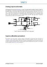
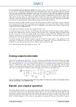
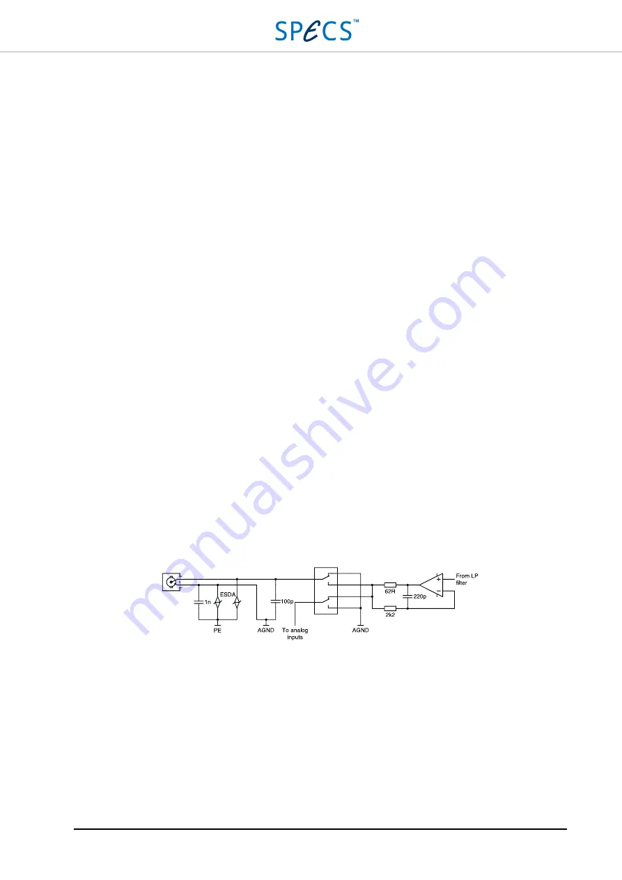
Analog outputs schematic
Each one of the eight analog outputs
(3) is referenced to AGND. This means that the shield of the output
BNC is not connected to PE, unless a BNC short plug is connected to the
SC5 as described in the
section. When the SC5 is set to calibration mode, all outputs are connected
directly to AGND with a relay. During normal operation the relay connects the output stage with the output
connector. The output stage consists of a 20-bit, 1 MS/s DAC, followed by a 5
th
order (Butterworth) active low-pass
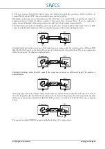
filter with a corner frequency of 40 kHz (-3 dB), and a buffer, which is shown in the picture below.
Figure 11: Schematic of the output stage of the SC5 analog outputs. The output relay is shown in the position when the
SC5 is not powered up or set to calibration mode.
Bipolar and unipolar operation
The analog outputs of the SC5 are configured by default for bipolar operation, meaning that the output voltage can
be set between -10 and +10 V. If only positive voltages from 0 to 10 V are required, each output channel can be
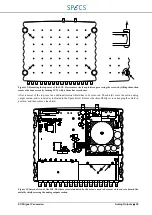
individually switched to unipolar operation. This requires changing the position of two jumpers per channel, which
are placed on the main circuit board of the SC5. One jumper connects the negative reference voltage input of the
DAC to AGND (instead of -10 V) while the other jumper is read out by the logic of the SC5 in order to
Summary of Contents for Nanonis SC5
Page 1: ...Signal Conversion SC5 User Manual November 2016 R6860...
Page 2: ......
Page 5: ...SC5 Signal Conversion Conventions 5...
Page 8: ......
Page 72: ......
Page 74: ......
Page 75: ...SC5 Signal Conversion Legal Information 75 Declaration of Conformity...

