SC5 Signal Conversion
Performance Measurements
•
65
Lock-in linearity
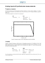
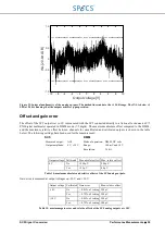
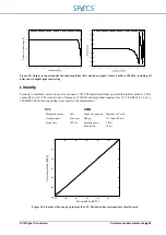
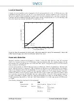
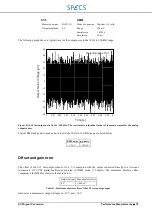
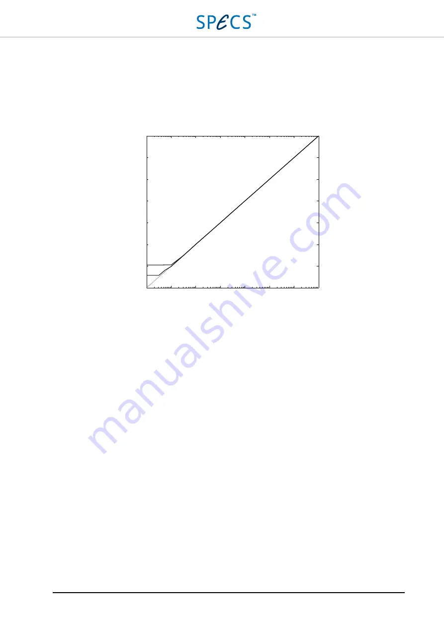
Linearity in lock-in amplifier mode is measured with AO1 connected directly to AI1. A 100 Hz sine wave with
amplitudes in the range between 1 µV and 10 V is generated from AO1, and the amplitude (or “R”) is detected by
the lock-in amplifier, which demodulates the signal at AI1. The lock-in amplifier uses a sync filter to measure the
amplitude, and the demodulated amplitude is then averaged 100 times (integration time of 1 s). The following graph
shows the linearity measurement with hrDAC™ switched on and off.
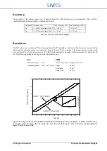
Figure 46: Linearity measurement in lock-in mode, with output connected to input. The measurement is shown with
hrDAC turned off (upper curve at the lower left corner) and on (lower curve).
Harmonic distortion
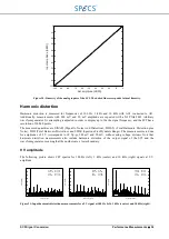
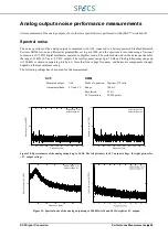
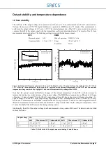
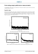
Harmonic distortion is measured for frequencies of 100 Hz, 1 kHz and 10 kHz with AO1 of the SC5 connected
directly to a
National Instruments 4472
PXI dynamic signal acquisition module. The sampling frequency for the
measurement is 20× the signal frequency for 100 Hz and 1 kHz, and 10× the signal frequency for 10 kHz. The FFT
has a resolution of 100 000 points.
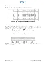
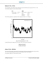
The measured quantities are SINAD (SIgnal to Noise And Distortion), THD+N (Total Harmonic Distortion plus
Noise), both measured over 5 harmonics, THD (Total Harmonic Distortion), and SFDR (Spurious Free Dynamic
Range). The measurements are done for amplitudes of 9 V (corresponds to 18 Vp-p), 900 mV and 90 mV, without
using voltage dividers. The input sensitivity of the acquisition module is 10 V for all measurements. Therefore,
SINAD and THD+N results for smaller signals suffer from the decrease in SNR of the acquisition module, which
has a noisefloor of more than 30 dB higher than the output noisefloor of the SC5. The acquisition module is
specified with a SFDR of 104 dB at 1 kHz and -1 dBFS input amplitude and a THD of -102 dBc (THD+N: -97 dBc,
50 kHz measurement bandwidth) at 1 kHz and -1 dBFS input amplitude. For 10 kHz input signals the THD reduces
to -95 dBc.
The following settings have been used for the measurement:
SC5
DAQ
Measured output:
AO1
Mode of operation: Digitizer, AC volts
Output signal:
Sinewave
Range:
10 V
Samplig rate:
2 kS/s, 20 kS/s,
100 kS/s
Resolution:
24 bit
-120
-140
-100
-80
-60
-40
-20
0
Set amplitude [dBFS]
hrDAC OFF
hrDAC ON
Lo
ck
-in
am
pl
itu
de
[d
B
FS
]
0
-20
-40
-60
-80
-100
-120
-140
Summary of Contents for Nanonis SC5
Page 1: ...Signal Conversion SC5 User Manual November 2016 R6860...
Page 2: ......
Page 5: ...SC5 Signal Conversion Conventions 5...
Page 8: ......
Page 72: ......
Page 74: ......
Page 75: ...SC5 Signal Conversion Legal Information 75 Declaration of Conformity...

