Vacuum Installation
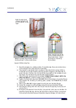
throughs are fixed with the locking screw during transport. Make sure to unlock
them before using the rotary feedthroughs and lock them again afterwards.
13. Adjust the analyzer at the vacuum chamber flange (Check section 4.4 “Align-
14. Bolt the analyzer at the vacuum system flange with the delivered screws, wash-
ers and nuts.
15.
For PHOIBOS150 and
μ
-
metal chambers
: Do not release the lifting gear until the
analyzer is supported by an additional supporting post!
16. Check the physical stability of the supporting post and the system frame and re-
lease the lifting gear.
17. Use the iris aperture and the analyzer view port to locate the real center posi-
tion of the lens with respect to the desired acceptance area on the sample.
18. Evacuate the chamber to a pressure of below 10
-5
Pa (10
-7
mbar) and bake out
(see section 4.6 “Baking Out” on page 43).
19. Check the vacuum before and after bakeout.
20. Connect the analyzer as described in the analyzer manual. (Figure 2: Connec-
tion Scheme page 7)
21. Before operating the analyzer wait for complete cool down (good thermal insu-
lation inside the analyzer leads to a complete cool down time of about 2-3 days,
at least 2 days cool down is recommended).
4.6 Baking Out
The vacuum chamber has to be baked out to get good UHV in a reasonable time. The
temperature during the bake can be up to 200° C. A reference thermocouple for the
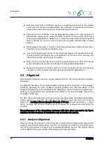
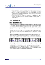
temperature measurement should be attached to the detector flange (
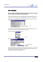
figure 24
)!
Figure 24: Detector Flange
Before baking out:
●
Switch off the HSA3500 control unit.
●
The analyzer box (fixed at the lens housing, see figure 4) should be removed as
well as,
●
the detector box (preamplifier) with connection cables (Channel HV, Channel
Base, CAN)
43
Thermocouple here
Summary of Contents for PHOIBOS 100
Page 1: ...PHOIBOS Hemispherical Energy Analyzer Series PHOIBOS 100 PHOIBOS 150 3 1...
Page 6: ...Table of Contents PHOIBOS...
Page 10: ...Introduction 4 PHOIBOS...
Page 13: ...Electrical Connections Figure 2 Connection Scheme PHOIBOS 7...
Page 14: ...Components and Connections Figure 3 Analyzer Housing PHOIBOS100 8 PHOIBOS...
Page 15: ...Electrical Connections Figure 4 Analyzer Housing PHOIBOS150 PHOIBOS 9...
Page 42: ......
Page 51: ...SpecsLab Hardware and Software Installation PHOIBOS 45...
Page 52: ......
Page 62: ......
Page 78: ...Analyzer Checks Figure 33 Schematics of the 12 pin Analyzer Feedthrough 72 PHOIBOS...
Page 80: ......
Page 86: ......
Page 92: ...List of Figures Figure 39 Alignment Pin 84 II PHOIBOS...
Page 93: ...List of Figures PHOIBOS III...
Page 94: ......
Page 96: ......
Page 98: ...Index PHOIBOS...

