Detailed Operation
●
For optimal lifetime, operate the detector at the minimum voltage necessary to
obtain an usable signal (see section 3.5.3, “Electron Multiplication” on page 27).
●
Microchannel plates and Channeltron detectors can be degraded by exposure to
various types of hydrocarbon materials which raise the work function of the sur-
face, causing gain degradation.
●
If channeltrons are operated at higher temperatures (> 340 K) they can suffer
damage. Some channeltrons will lose gain and exhibit a markedly higher de-
tector plateau.
5.3.3 Functional Test
5.3.3.1 XPS (AES/UPS) Operation
To begin, the detector unit should have already been baked out. A silver sample with a
size not smaller than 5×14 mm
2
should have been transferred into the vacuum cham-
ber. The sample has to be cleaned by sputtering. The base pressure should be lower
than 10
-7
mbar (10
-5
Pa) to avoid a damage to the detector by sparks. For special reas-
ons, e.g. for depth profiling with noble gas ions, operation up to 10
-6
mbar (10
-4
Pa) is
allowed.
Adjust the detector voltage to the value corresponding to the Specification Report of
the analyzer or check the actual value (see “The Working Point of the CEM’s” on page
27).
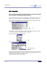
Measure a wide energy XPS spectrum scanning the kinetic energy of the particles from
200 to 1.5 keV, e.g. with an energy step of 500meV and in FixedAnalyzerTransmission
mode with pass energy of ~10-20.0 eV (Figure 31: XPS on Silver, Wide Scan (PHOIBOS
150 MCD9), page 67).
Group Region
Method Lens Slit
Mode Scans Dwell
Delta E
exc
E
kin
E
pass
U
bias
U
det
300W Overview
300W, MA13
XPS
MA 2:7x20
\2:open
FAT
1
0.01
0.3
1253.6 200 – 1267.4 13
90
1950
In a first rough test without careful adjustment one should get few 10
4
cps at the Ag
3d
5/2
peak using 100 W Mg K
α
X-ray source power.
If not, check the photoemission sample current, which should be in the range of 25-40
nA for 100 W Mg K
α
. Secondly, check the MCD voltage, and the discriminator level of
the MCD preamplifier. Also check whether the intensity of the C- and O-peaks are small
enough. Otherwise the sample should be sputtered once more.
49
Summary of Contents for PHOIBOS 100
Page 1: ...PHOIBOS Hemispherical Energy Analyzer Series PHOIBOS 100 PHOIBOS 150 3 1...
Page 6: ...Table of Contents PHOIBOS...
Page 10: ...Introduction 4 PHOIBOS...
Page 13: ...Electrical Connections Figure 2 Connection Scheme PHOIBOS 7...
Page 14: ...Components and Connections Figure 3 Analyzer Housing PHOIBOS100 8 PHOIBOS...
Page 15: ...Electrical Connections Figure 4 Analyzer Housing PHOIBOS150 PHOIBOS 9...
Page 42: ......
Page 51: ...SpecsLab Hardware and Software Installation PHOIBOS 45...
Page 52: ......
Page 62: ......
Page 78: ...Analyzer Checks Figure 33 Schematics of the 12 pin Analyzer Feedthrough 72 PHOIBOS...
Page 80: ......
Page 86: ......
Page 92: ...List of Figures Figure 39 Alignment Pin 84 II PHOIBOS...
Page 93: ...List of Figures PHOIBOS III...
Page 94: ......
Page 96: ......
Page 98: ...Index PHOIBOS...


