Unit Operation
5.3.3.2 ISS Operation
Please read these instructions carefully. Damage of channeltrons and ampli-
fier are possible if the following is done incorrectly!
Set the detector voltage to the value corresponding to the Specification Report of the
analyzer or check the actual value (“The Working Point of the CEM’s” on page 27).
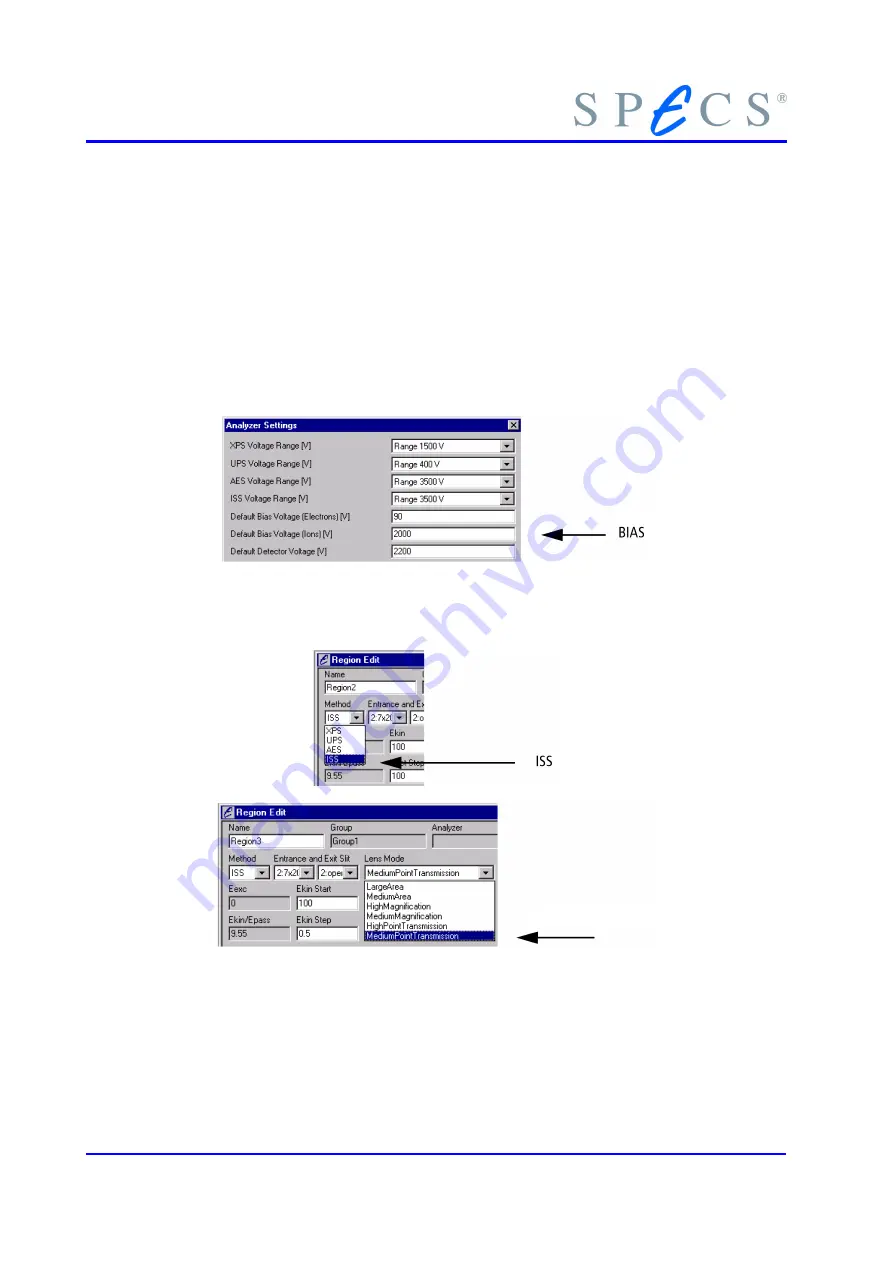
The conversion voltage (BIAS) in the Analyzer Settings window is default set to 2000
(see section 3.5.4, “Conversion Energy” on page 32).
The excitation source should be degassed and run under proper conditions to avoid
structures due to possible residual gas inside the sputter line.
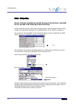
Switch the method to ISS mode in SpecsLab.
Recommended lens mode: Point Transmission.
Optimize the excitation source with typical sample current of less than 1
μ
A. Select the
FixedEnergies Analyzer Mode and choose a kinetic energy with measurable counts to
maximize intensity with the source deflection tools.
Check the function with an overview spectra.
50
Point Transmission
Summary of Contents for PHOIBOS 100
Page 1: ...PHOIBOS Hemispherical Energy Analyzer Series PHOIBOS 100 PHOIBOS 150 3 1...
Page 6: ...Table of Contents PHOIBOS...
Page 10: ...Introduction 4 PHOIBOS...
Page 13: ...Electrical Connections Figure 2 Connection Scheme PHOIBOS 7...
Page 14: ...Components and Connections Figure 3 Analyzer Housing PHOIBOS100 8 PHOIBOS...
Page 15: ...Electrical Connections Figure 4 Analyzer Housing PHOIBOS150 PHOIBOS 9...
Page 42: ......
Page 51: ...SpecsLab Hardware and Software Installation PHOIBOS 45...
Page 52: ......
Page 62: ......
Page 78: ...Analyzer Checks Figure 33 Schematics of the 12 pin Analyzer Feedthrough 72 PHOIBOS...
Page 80: ......
Page 86: ......
Page 92: ...List of Figures Figure 39 Alignment Pin 84 II PHOIBOS...
Page 93: ...List of Figures PHOIBOS III...
Page 94: ......
Page 96: ......
Page 98: ...Index PHOIBOS...


