Specification Check
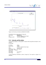
The signal (net intensity, i.e. peak count above background) of the Ag 3d
5/2
peak is
about 85-200 kcps/channel depending on the sample to X-ray source distance. The back-
ground in this case is defined as a straight line between the two neighbouring valleys
on both sides of the peak. The FWHM of the Ag 3d
5/2
peak is calculated by measuring
the peak width at the half height between the peak maximum and the background.
Note
:
Because of considerable spread in the gain of different CEM‘s, the voltage required for
the signal may differ from the specifications (see section 9.2). Pay attention to the de-
tector voltage value in the Specification Report for the analyzer. Monitor the aging of
the channeltrons monthly and adjust the default detector voltage.
If the measured spectra and values differ substantially from those in the Specification
Report of the analyzer, it may be necessary to sputter the sample again or optimize the
sample and X-ray source positions, or a HSA 3500 calibration might be needed. Oxida-
tion of the anode material may also lead to peak broadening.
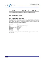
In many cases it is helpful to know the intensities, signals, and accompanying FWHMs at
different pass energies. The measurements described above should be made at pass en-
ergies e.g. of 2, 5, 10, 20 and 50eV for largest slit and up to 200 eV for the 1mm slit dia-
meter. The Dwell Time or number of scans should be adapted to the pass energies in
such a way that the maximum intensities (in counts not in counts per second) are about
the same in every case. Namely, for low pass energies, choose a higher Dwell Time than
for high pass energies. This gives comparable counting statistics for all measurements.
69
Summary of Contents for PHOIBOS 100
Page 1: ...PHOIBOS Hemispherical Energy Analyzer Series PHOIBOS 100 PHOIBOS 150 3 1...
Page 6: ...Table of Contents PHOIBOS...
Page 10: ...Introduction 4 PHOIBOS...
Page 13: ...Electrical Connections Figure 2 Connection Scheme PHOIBOS 7...
Page 14: ...Components and Connections Figure 3 Analyzer Housing PHOIBOS100 8 PHOIBOS...
Page 15: ...Electrical Connections Figure 4 Analyzer Housing PHOIBOS150 PHOIBOS 9...
Page 42: ......
Page 51: ...SpecsLab Hardware and Software Installation PHOIBOS 45...
Page 52: ......
Page 62: ......
Page 78: ...Analyzer Checks Figure 33 Schematics of the 12 pin Analyzer Feedthrough 72 PHOIBOS...
Page 80: ......
Page 86: ......
Page 92: ...List of Figures Figure 39 Alignment Pin 84 II PHOIBOS...
Page 93: ...List of Figures PHOIBOS III...
Page 94: ......
Page 96: ......
Page 98: ...Index PHOIBOS...

