Spectrometer
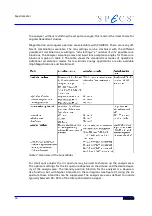
angle-resolving is accomplished with an Iris aperture in the diffraction plane of the lens
system. using the Iris the angular resolution can be continously adjusted while keeping
the acceptance area on the sample constant.
The transmission modes are optimized for high transmission at different spot sizes of
the source. The lateral resolution is worsened and the acceptance area normally not
defined by the lens.
In the angular dispersive modes, the emission angle distribution is imaged instead of
the real image. All lateral resolution is lost, but instead the emission angle information
is easily available. These modes are intended for UPS band mapping, Fermi surface map-
ping or similar experiments.
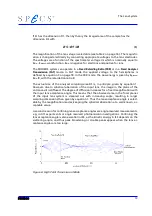
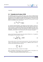
In the hemispherical capacitor, the particles passing through the entrance slit S1 are fo-
cused onto the capacitor output plane S2. The radial position of the slit image in plane
S2 depends on the kinetic energy of the particles in the capacitor. Particles on the cent-
ral trajectory possess the nominal pass energy. They are focused to the central radial
position at the exit plane S2. Particles with higher kinetic energy are focused further
outside, and particles with lower energy are focused further inside in plane S2. This of-
fers the possibility of multichannel detection, with simultaneous recording of an energy
band around the nominal pass energy. Particles passing through the capacitor output
plane S2 are accelerated onto the detector system C. With the multichannel detector,
each channel is connected to a separate preamplifier mounted outside the vacuum. The
preamplifiers are read out by the Multi Channel Detector (MCD) counter interface of
the SPECS data acquisition software.
3.1 The Lens System
The multi-element, two-stage transfer lens was designed to yield ultimate transmission
and well-defined optical properties. It may be operated in several different modes for
angular and spatially resolved studies to adapt the analyzer to different tasks. All lens
modes can be set electronically.
A lens system with the variable Slit Orbit mechanism is necessary to
●
image the sample plane on the HSA entrance plane
●
define the analyzed sample area and the accepted solid angle on a sample,
●
accelerate / decelerate the particles with the observed energy to the pass en-
ergy.
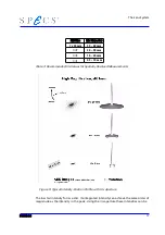
The standard working distance of 40 mm and the 44° conical shape of the front part of
the lens provide optimum access to the sample for all kinds of excitation sources. At the
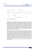
lens stage, the particles emerging from the sample S are imaged onto the entrance slit
S1, with the sample being in the focal plane of the lens system, i.e. 40 mm in front of
the first lens electrode T1. Inside the lens stage the particles pass through an intermedi-
ate image before they are focused onto the input slit S1 of the hemispherical capacitor
(figure 5). At S1 the particles have been retarded by the energy difference between the
nominal particle kinetic energy E
kin
and the nominal pass energy E
pass
.
12
Summary of Contents for PHOIBOS 100
Page 1: ...PHOIBOS Hemispherical Energy Analyzer Series PHOIBOS 100 PHOIBOS 150 3 1...
Page 6: ...Table of Contents PHOIBOS...
Page 10: ...Introduction 4 PHOIBOS...
Page 13: ...Electrical Connections Figure 2 Connection Scheme PHOIBOS 7...
Page 14: ...Components and Connections Figure 3 Analyzer Housing PHOIBOS100 8 PHOIBOS...
Page 15: ...Electrical Connections Figure 4 Analyzer Housing PHOIBOS150 PHOIBOS 9...
Page 42: ......
Page 51: ...SpecsLab Hardware and Software Installation PHOIBOS 45...
Page 52: ......
Page 62: ......
Page 78: ...Analyzer Checks Figure 33 Schematics of the 12 pin Analyzer Feedthrough 72 PHOIBOS...
Page 80: ......
Page 86: ......
Page 92: ...List of Figures Figure 39 Alignment Pin 84 II PHOIBOS...
Page 93: ...List of Figures PHOIBOS III...
Page 94: ......
Page 96: ......
Page 98: ...Index PHOIBOS...


