The Lens System
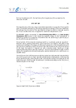
If S1 has the dimension D1, then by theory the imaged area of the sample has the
dimension DS with
DS
=
D1
/
M
(1)
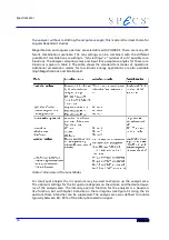
The magnification of the lens stage is selectable (see table 2 on page 16). The magnific-
ation is changed electrically by connecting appropriate voltages to the lens electrodes.
The voltages are a function of the spectrometer voltage U
0
which is nominally equal to
E
kin
- E
pass
+ workfunction. E
kin
is negative for electrons and positive for ions.
The PHOIBOS system can operate in a
Fixed Retarding Ratio (FRR)
or in a
Fixed Analyzer
Transmission (FAT)
mode. In FAT mode the applied voltage to the hemispheres is
defined by equation 3 on page 18. In the FRR mode, the pass energy is given by E
pass
=
E
kin
/R, with the retardation ratio R.
The actual size of the analyzer sampling area DS is, in principle, given by equation 1.
However, due to spherical aberration of the input lens, the image in the plane of the
entrance slit is diffused. The degree of diffusion increases for a fixed magnification with
the input lens acceptance angle. This means that the observed area in the focal planes
of the input lens system is smeared out with increasing angle, resulting in larger
sampling dimensions than given by equation 1. Thus the lens acceptance angle is select-
able by the magnification modes, keeping the spherical aberration at a well known, ac-
ceptable value.
A second reason for confining lens acceptance angles are angle-resolved measurements,
e.g. in tilt experiments or angle resolved photoemission investigations. Confining the
lens acceptance angle is also essential in ISS, as the kinetic energy in ISS depends on the
scattering angle, and thus peak broadening or double peaks appear when the lens ac-
ceptance angles are too large.
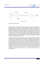
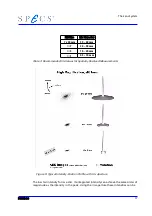
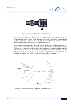
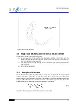
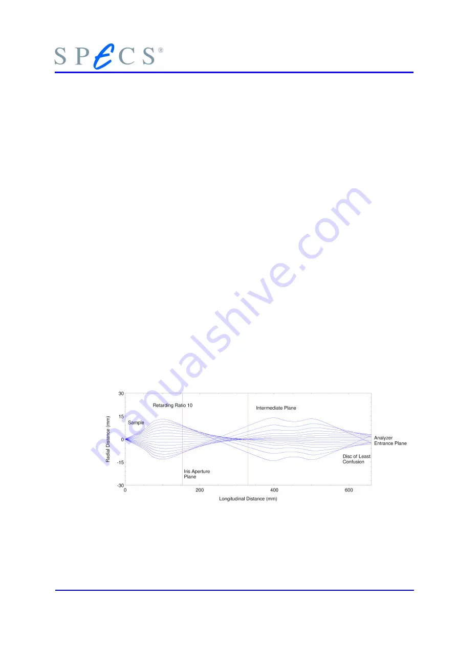
Figure 6: High Point Transmission Mode
13
Summary of Contents for PHOIBOS 100
Page 1: ...PHOIBOS Hemispherical Energy Analyzer Series PHOIBOS 100 PHOIBOS 150 3 1...
Page 6: ...Table of Contents PHOIBOS...
Page 10: ...Introduction 4 PHOIBOS...
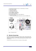
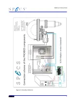
Page 13: ...Electrical Connections Figure 2 Connection Scheme PHOIBOS 7...
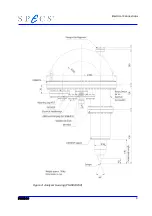
Page 14: ...Components and Connections Figure 3 Analyzer Housing PHOIBOS100 8 PHOIBOS...
Page 15: ...Electrical Connections Figure 4 Analyzer Housing PHOIBOS150 PHOIBOS 9...
Page 42: ......
Page 51: ...SpecsLab Hardware and Software Installation PHOIBOS 45...
Page 52: ......
Page 62: ......
Page 78: ...Analyzer Checks Figure 33 Schematics of the 12 pin Analyzer Feedthrough 72 PHOIBOS...
Page 80: ......
Page 86: ......
Page 92: ...List of Figures Figure 39 Alignment Pin 84 II PHOIBOS...
Page 93: ...List of Figures PHOIBOS III...
Page 94: ......
Page 96: ......
Page 98: ...Index PHOIBOS...


