Spectrometer
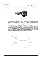
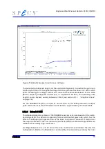
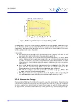
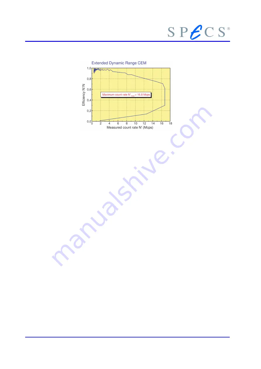
Figure 18: Efficiency Plot for the new Extended Range CEM
From a spectral ratio plot of two spectra measured at different beam currents the de-
tector efficiency N’ / N was calculated. With increasing count rate the mean gain of the
pulse height distribution will decrease. For some critical value the distribution starts to
fall below the discriminator threshold.
Conclusions:
●
The maximum (measured) count rate detectable is 5.6 Mcps per channel for the
standard CEMs and 16.8 Mcps for the extended range CEMs.
●
The linearity and the non-extended dead time behavior for the standard CEMs
up to 1 Mcps and for the extended range CEMs up to 10 Mcps true count rate is
verified. Up to these count rates no significant deviation from linearity could be
observed with the PHOIBOS detection system (CEMs and PCU 300 detection
electronics).
●
From pulse height distribution measurements the findings are that the mean
gain from the extended range CEMs is much less sensitive to increases in the
true count rate. This is the reason for the extended working range.
●
The detector voltage required to operate the extended range type CEMs is 300
V higher than that for the standard CEMs.
●
The high current AES survey spectrum shows the high count rate capability of
the PHOIBOS detection system with the extended dynamic range CEMs.
3.5.4 Conversion Energy
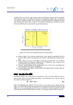
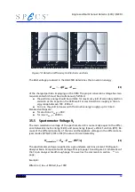
The detection efficiency of a CEM with respect to a particle is defined as the probability
of this particle or photon producing an output pulse. The detection efficiency curves for
electrons, positive ions and UV-light in figure 19 are based on published data and allow
an approximate estimation of the efficiency in the given energy and wavelength range.
32
Summary of Contents for PHOIBOS 100
Page 1: ...PHOIBOS Hemispherical Energy Analyzer Series PHOIBOS 100 PHOIBOS 150 3 1...
Page 6: ...Table of Contents PHOIBOS...
Page 10: ...Introduction 4 PHOIBOS...
Page 13: ...Electrical Connections Figure 2 Connection Scheme PHOIBOS 7...
Page 14: ...Components and Connections Figure 3 Analyzer Housing PHOIBOS100 8 PHOIBOS...
Page 15: ...Electrical Connections Figure 4 Analyzer Housing PHOIBOS150 PHOIBOS 9...
Page 42: ......
Page 51: ...SpecsLab Hardware and Software Installation PHOIBOS 45...
Page 52: ......
Page 62: ......
Page 78: ...Analyzer Checks Figure 33 Schematics of the 12 pin Analyzer Feedthrough 72 PHOIBOS...
Page 80: ......
Page 86: ......
Page 92: ...List of Figures Figure 39 Alignment Pin 84 II PHOIBOS...
Page 93: ...List of Figures PHOIBOS III...
Page 94: ......
Page 96: ......
Page 98: ...Index PHOIBOS...

