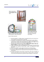
Mounting the Detector
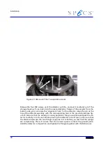
Figure 22: Corresponding Hole in the Ground Plate
4.3 Achieve the Maximum Lifetime of a Channel Elec-
tron Multiplier
To achieve the maximum lifetime of a channel electron multiplier the rules listed below
should be strictly followed.
●
After a bakeout, the analyzer needs 2-3 days to cool down. If channel electron
multipliers are operated at higher temperatures (> 60° C) they can suffer severe
damage. Some channel electron multipliers will lose gain and exhibit a
markedly higher detector plateau.The interior parts of the PHOIBOS will cool
down significantly slower than the housing. It is recommended to wait for a
complete cool down of the detector assembly; at least 2 days. Even if the ana-
lyzer housing is cold, any internal parts on insulators may still be too hot for
safe operation. It is imperative that all users are aware of the issue and take the
necessary precautions.
●
During first use after bake out, rapid desorption of surface adsorbed gas will oc-
cur from the walls of the channel electron multipliers, so care should be taken
not to use the detector at full channel electron multiplier voltage and full in-
tensity within the first few hours of operation. We recommend to increase the
detector voltage over a period of 1.5 hours up to the recommended value. Use
the SpecsLab mode Detector Voltage Scan and set start, end, step and dwell
time parameter for this procedure.
●
During the first few days of operation of a new detector, it is recommended
that high output currents are avoided (i.e. inputs above 1 Mcps). Taking this ini-
tial burn-in precaution can prevent premature failure.
●
Choose a moderate value of the detector voltage to prevent rapid ageing of the
detector. The optimum operating point is about 50 - 100 V beyond the plateau
of the intensity versus detector voltage sweep, not more.
39
Summary of Contents for PHOIBOS 100
Page 1: ...PHOIBOS Hemispherical Energy Analyzer Series PHOIBOS 100 PHOIBOS 150 3 1...
Page 6: ...Table of Contents PHOIBOS...
Page 10: ...Introduction 4 PHOIBOS...
Page 13: ...Electrical Connections Figure 2 Connection Scheme PHOIBOS 7...
Page 14: ...Components and Connections Figure 3 Analyzer Housing PHOIBOS100 8 PHOIBOS...
Page 15: ...Electrical Connections Figure 4 Analyzer Housing PHOIBOS150 PHOIBOS 9...
Page 42: ......
Page 51: ...SpecsLab Hardware and Software Installation PHOIBOS 45...
Page 52: ......
Page 62: ......
Page 78: ...Analyzer Checks Figure 33 Schematics of the 12 pin Analyzer Feedthrough 72 PHOIBOS...
Page 80: ......
Page 86: ......
Page 92: ...List of Figures Figure 39 Alignment Pin 84 II PHOIBOS...
Page 93: ...List of Figures PHOIBOS III...
Page 94: ......
Page 96: ......
Page 98: ...Index PHOIBOS...

