Installation
●
Backstreaming from oil diffusion pumps or roughing pumps has to be avoided
at all costs. It is strictly recommended to use cold traps and molecular sieve traps
and maintain them according to manufacturers specifications.
●
Channel electron multipliers can be degraded by exposure to various types of
hydrocarbon gases which raises the work function of the surface and hence
causing gain degradation. Operation in a clean vacuum environment of 5×10⁻⁸
mbar or better is a must in order to ensure the long-life characteristics of these
devices.
●
Other gases containing F, S and Cl, which may decompose under electron bom-
bardment must not enter the detector area.
●
Due to the hygroscopic nature of the doped lead glass, it is important that the
channel electron multipliers are not exposed to air for more than one day. Dry
nitrogen should be used to vent the system.
●
High intensity sources like electron sources needs special care. Start with lowest
source strength and narrow slit settings to avoid possible degradation.
●
Measurements at the secondary electron cut-off needs special care. Use low pass
energies (3- 5 eV) and small slit settings to avoid possible degradation.
4.4 Alignment
Non-shielded chambers need no special modification of the lens protection (analyzer
shielding).
For shielded chambers, the shielding needs a good physical connection to the analyzer
shielding, especially for slow (<100eV) charged particles. The insertion depth of the
analyzer shielding has to be modified if the shielding is too far inside the chamber (nor-
mally by a non-magnetic lens protection cap added to the lens shielding). Please con-
tact SPECS in this case.
For XPS, the distance between the X-ray source and the sample should be minimized to
obtain maximum count rates. The distance between the sample and the lens T1 must be
fixed to the working distance (sample distance) of 40 mm (see also section 4.4 , "Align-
ment" on page 40). None of these three parts should be in physical contact with one
another.
The performance of the channeltron decreases with time when exposed to air. Try to
minimize the time between its installation and evacuation the system.
4.4.1 Analyzer Alignment
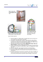
After mounting the analyzer on the chamber a check of the sample positioning via the
analyzer viewport should be done. Use the iris aperture to locate the real center posi-
tion of the lens system in respect to the desired acceptance area on the sample. Please
contact SPECS if you see a visible offset between this two positions.
40
Summary of Contents for PHOIBOS 100
Page 1: ...PHOIBOS Hemispherical Energy Analyzer Series PHOIBOS 100 PHOIBOS 150 3 1...
Page 6: ...Table of Contents PHOIBOS...
Page 10: ...Introduction 4 PHOIBOS...
Page 13: ...Electrical Connections Figure 2 Connection Scheme PHOIBOS 7...
Page 14: ...Components and Connections Figure 3 Analyzer Housing PHOIBOS100 8 PHOIBOS...
Page 15: ...Electrical Connections Figure 4 Analyzer Housing PHOIBOS150 PHOIBOS 9...
Page 42: ......
Page 51: ...SpecsLab Hardware and Software Installation PHOIBOS 45...
Page 52: ......
Page 62: ......
Page 78: ...Analyzer Checks Figure 33 Schematics of the 12 pin Analyzer Feedthrough 72 PHOIBOS...
Page 80: ......
Page 86: ......
Page 92: ...List of Figures Figure 39 Alignment Pin 84 II PHOIBOS...
Page 93: ...List of Figures PHOIBOS III...
Page 94: ......
Page 96: ......
Page 98: ...Index PHOIBOS...

