Chapter
6
Troubleshooting
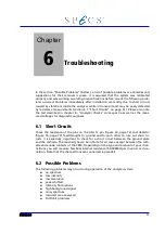
In the section “Possible Problems” (below), a list of possible problems or anomalies and
suggestions for their removal is given. It is assumed that the system was calibrated
properly and was working according to specifications before one of the following prob-
lems occurred. Problems immediately after installation are mostly due to short circuits
caused by vibrations inside the analyzer while in transport and may be easily detected
by resistance measurements (section 6.1 “Short Circuits” on page 51). Please also note
the test described in chapter 8 - "Analyzer Checks" some spectra as well as the meas-
ured voltages for diagnostic purposes.
6.1 Short Circuits
Check the resistance of the pins on the HSA 12-pin (figure 33, page 72) and detector
(figure 34, page 73) feedthroughs to ground and to each other to rule out short cir-
cuits. It is especially important to check for a short circuit between the ground plate
and the cathode. The resistivity has to be infinite for all cases, except between the cath-
ode and anode contacts of the CEM, Depending on the type and amount of your chan-
neltrons you will measure few M
Ω
internal resistance (50-300M
Ω
per channel or chan-
neltron. Note that the channeltrons are connected in parallel).
6.2 Possible Problems
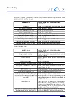
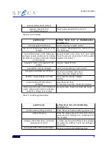
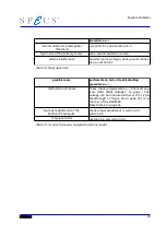
The following problems may occur during operation of the analyzer system:
●
no spectrum
●
low intensity
●
low resolution
●
peaks shifted
●
intensity fluctuations
●
high background signal
●
noisy spectrum
●
incorrect area analyzed
●
Slit Orbit problems
51
Summary of Contents for PHOIBOS 100
Page 1: ...PHOIBOS Hemispherical Energy Analyzer Series PHOIBOS 100 PHOIBOS 150 3 1...
Page 6: ...Table of Contents PHOIBOS...
Page 10: ...Introduction 4 PHOIBOS...
Page 13: ...Electrical Connections Figure 2 Connection Scheme PHOIBOS 7...
Page 14: ...Components and Connections Figure 3 Analyzer Housing PHOIBOS100 8 PHOIBOS...
Page 15: ...Electrical Connections Figure 4 Analyzer Housing PHOIBOS150 PHOIBOS 9...
Page 42: ......
Page 51: ...SpecsLab Hardware and Software Installation PHOIBOS 45...
Page 52: ......
Page 62: ......
Page 78: ...Analyzer Checks Figure 33 Schematics of the 12 pin Analyzer Feedthrough 72 PHOIBOS...
Page 80: ......
Page 86: ......
Page 92: ...List of Figures Figure 39 Alignment Pin 84 II PHOIBOS...
Page 93: ...List of Figures PHOIBOS III...
Page 94: ......
Page 96: ......
Page 98: ...Index PHOIBOS...


