Calibration
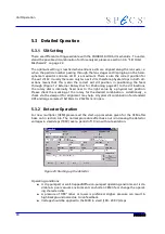
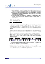
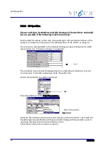
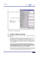
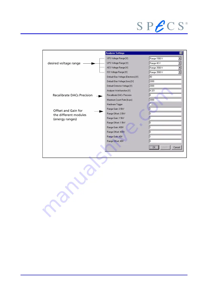
Figure 26: Menu - “Analyzer Settings”
7.1 Complete Calibration Procedure
A complete calibration procedure consists of (see Figure 27: Analyzer Cailbration Pro-
cedure page 59):
1. Check/set offset and gain with voltmeter, i.e. the calibration of the modules via
high precision voltmeter and high voltage probe (section on page )
2. “MCD Calibration” , i.e. the estimation of the energy shifts of the single chan-
nels for selectable slit/lens combinations (see section 7.3 on page 60), which in-
cludes the calibration of the peak position independent of pass energy (see sec-
If the achieved values differ substantially from the existing default values or a
strong dependence on pass energy is observed for the spectra, this can point out
an analyzer malfunction which can not be corrected by the calibration procedure.
Please contact SPECS and send some spectra to assist in diagnosis.
3. the estimation of the analyzer workfunction (see section 7.4 on page 61) and
fine tuning of the offset for all modules (except 40V) via Fermi edge measure-
ments (Figure 29: Fermi Edge Operation page 62) and optionally
58
Summary of Contents for PHOIBOS 100
Page 1: ...PHOIBOS Hemispherical Energy Analyzer Series PHOIBOS 100 PHOIBOS 150 3 1...
Page 6: ...Table of Contents PHOIBOS...
Page 10: ...Introduction 4 PHOIBOS...
Page 13: ...Electrical Connections Figure 2 Connection Scheme PHOIBOS 7...
Page 14: ...Components and Connections Figure 3 Analyzer Housing PHOIBOS100 8 PHOIBOS...
Page 15: ...Electrical Connections Figure 4 Analyzer Housing PHOIBOS150 PHOIBOS 9...
Page 42: ......
Page 51: ...SpecsLab Hardware and Software Installation PHOIBOS 45...
Page 52: ......
Page 62: ......
Page 78: ...Analyzer Checks Figure 33 Schematics of the 12 pin Analyzer Feedthrough 72 PHOIBOS...
Page 80: ......
Page 86: ......
Page 92: ...List of Figures Figure 39 Alignment Pin 84 II PHOIBOS...
Page 93: ...List of Figures PHOIBOS III...
Page 94: ......
Page 96: ......
Page 98: ...Index PHOIBOS...


