Calibration
well as sample charging or contamination of the surfaces inside the analyzer can influ-
ence your calibration.
Perform a manual “Recalibrate DAC” procedure to increase the accuracy to the possible
maximum if you have already warmed up the supply for at least 1 hour (e.g. type in a
value of 64).
7.3 MCD Calibration
SpecsLab2 software supports a calibration procedure named “MCD Calibration” in the
“Tools” menu. (The procedure should be used for the calibration of single channel de-
tectors also.) Because of the energy shift between the single channels for a given kinet-
ic energy (section 3.2 , "Hemispherical Analyzer (HSA)" on page 18) and the depend-
ence of the transmitted energy range of
α
(acceptance angle, see equation 5, page 18)
the detector shifts are different for each lens / slit combination. For the most common
lens / slit combinations, the values defined by SPECS and implemented in the software
give a good approximation. Nevertheless, the most commonly used lens / slit combina-
tions should be calibrated by the customer again to prevent loss of performance.
You can easily check that the values are correct if you display the single channels and
compare the energy position of each channel. Second compare two different pass ener-
gies. Large differences suggest the need to calibrate this lens / slit combination as de-
scribed below:
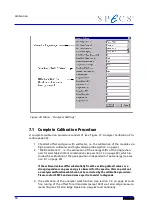
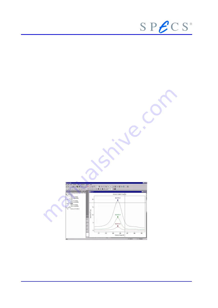
1. Identify a single high intensity peak in your data and set up a region that only
measures this peak.
2. Open a separate group with identical regions except pass energy for a single
peak within the region (e.g. pass energies 10, 20, 30eV).
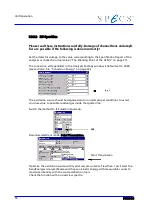
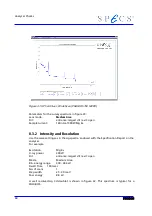
Figure 28: MCD Calibration
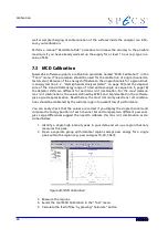
3. Measure the regions.
4. Select the tool MCD Calibration in the “Tool” menu.
5. Calculate the ’E
k
shift /E
p
’ by pressing “Calculate” button.
60
Summary of Contents for PHOIBOS 100
Page 1: ...PHOIBOS Hemispherical Energy Analyzer Series PHOIBOS 100 PHOIBOS 150 3 1...
Page 6: ...Table of Contents PHOIBOS...
Page 10: ...Introduction 4 PHOIBOS...
Page 13: ...Electrical Connections Figure 2 Connection Scheme PHOIBOS 7...
Page 14: ...Components and Connections Figure 3 Analyzer Housing PHOIBOS100 8 PHOIBOS...
Page 15: ...Electrical Connections Figure 4 Analyzer Housing PHOIBOS150 PHOIBOS 9...
Page 42: ......
Page 51: ...SpecsLab Hardware and Software Installation PHOIBOS 45...
Page 52: ......
Page 62: ......
Page 78: ...Analyzer Checks Figure 33 Schematics of the 12 pin Analyzer Feedthrough 72 PHOIBOS...
Page 80: ......
Page 86: ......
Page 92: ...List of Figures Figure 39 Alignment Pin 84 II PHOIBOS...
Page 93: ...List of Figures PHOIBOS III...
Page 94: ......
Page 96: ......
Page 98: ...Index PHOIBOS...


