Calibration
voltmeter precision and poor grounding of the sample can falsify the calibra-
tion!
The work function correction will be applied to all modules!
6. Check the result with new spectra.
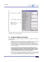
Figure 29: Fermi Edge Operation
Note the advice given in section 7.2 , "Recalibrate the DAC Precision" on page 59
For more detailed information please contact SPECS support.
7.5 Work Function Calibration with XPS
Please note the comments given in section 3.6, “Work Function” on page 34 and in the
description in section 7.4.
Instead of the UV excitation (section 7.4), X-ray excitation is used to calibrate the Work
Function. Note that you have to select at least the 1500V range ( see SpecsLab2 menu
’Analyzer/Settings’) in case of Mg/Al Kalpha excitation. This voltage ranges has a lower
accuracy than the 40V range ( on page ).
7.6 Offset Calibration with UPS
UV excitation recommended. Please note the comments given in the paragraph “Work
Function” on page 35 and the comments given in section 7.4.
Thermal or other effects can change the accuracy of the offset and gain over time. This
can be compensated for with the software. The values for the energy ranges can be
changed separately in the Menu ’Analyzer/Settings’, see Figure 26. The procedure de-
scribed in “Work Function Calibration with UPS” on page 58 as well as section , "" on
page should be done first if there are any doubts about the supply’s accuracy or the
Work Function setting.
62
Summary of Contents for PHOIBOS 100
Page 1: ...PHOIBOS Hemispherical Energy Analyzer Series PHOIBOS 100 PHOIBOS 150 3 1...
Page 6: ...Table of Contents PHOIBOS...
Page 10: ...Introduction 4 PHOIBOS...
Page 13: ...Electrical Connections Figure 2 Connection Scheme PHOIBOS 7...
Page 14: ...Components and Connections Figure 3 Analyzer Housing PHOIBOS100 8 PHOIBOS...
Page 15: ...Electrical Connections Figure 4 Analyzer Housing PHOIBOS150 PHOIBOS 9...
Page 42: ......
Page 51: ...SpecsLab Hardware and Software Installation PHOIBOS 45...
Page 52: ......
Page 62: ......
Page 78: ...Analyzer Checks Figure 33 Schematics of the 12 pin Analyzer Feedthrough 72 PHOIBOS...
Page 80: ......
Page 86: ......
Page 92: ...List of Figures Figure 39 Alignment Pin 84 II PHOIBOS...
Page 93: ...List of Figures PHOIBOS III...
Page 94: ......
Page 96: ......
Page 98: ...Index PHOIBOS...

