Analyzer Checks
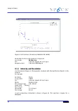
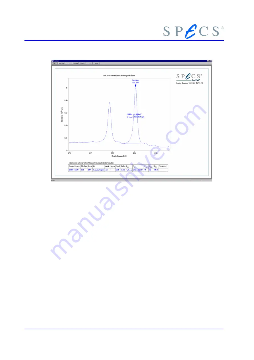
Figure 32: XPS on Silver, Ag 3d (PHOIBOS 150 MCD9)
Parameter for the Ag 3d spectrum in figure 34:
Lens mode:
Medium Area
Slit:
2:7 x 20 mm / 2:open
Sample current:
160 nA 300W Mg K
α
Detector voltage:
1950 V
If no spectrum but a straight line appears after the control unit has been started, either
no pulses are arriving at the control unit counter, the counter is defective, or the spec-
trometer voltage U
0
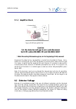
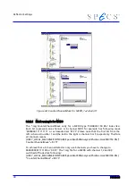
is missing. The following checks should be made:
1. All cable connections (Figure 2: Connection Scheme page 7) between has 3500
and Detection box PCU 300 the computer and the EC10 Ethernet-Can-Adapter.
2. Control Unit Check, see section
3. Preamplifier, see section 9.1
4. Section 9.2, “Detector Voltage” on page 76.
8.4 Connection Check of the Analyzer Electrodes
In addition to this test, the correct generation of the spectrometer voltages should be
checked (see section , "" on page ).
70
Summary of Contents for PHOIBOS 100
Page 1: ...PHOIBOS Hemispherical Energy Analyzer Series PHOIBOS 100 PHOIBOS 150 3 1...
Page 6: ...Table of Contents PHOIBOS...
Page 10: ...Introduction 4 PHOIBOS...
Page 13: ...Electrical Connections Figure 2 Connection Scheme PHOIBOS 7...
Page 14: ...Components and Connections Figure 3 Analyzer Housing PHOIBOS100 8 PHOIBOS...
Page 15: ...Electrical Connections Figure 4 Analyzer Housing PHOIBOS150 PHOIBOS 9...
Page 42: ......
Page 51: ...SpecsLab Hardware and Software Installation PHOIBOS 45...
Page 52: ......
Page 62: ......
Page 78: ...Analyzer Checks Figure 33 Schematics of the 12 pin Analyzer Feedthrough 72 PHOIBOS...
Page 80: ......
Page 86: ......
Page 92: ...List of Figures Figure 39 Alignment Pin 84 II PHOIBOS...
Page 93: ...List of Figures PHOIBOS III...
Page 94: ......
Page 96: ......
Page 98: ...Index PHOIBOS...


