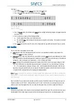
Please note the following conditions when setting phi and theta:
■
If the sample is not tilted in relation to the ion source, the angle theta is the inclination angle of the source flange.
■
If the sample is tilted, both angles relative to the position of the 4-pin feedthrough have to be estimated by the
operator to provide an optimum performance during the sputter process.
■
Theta is positive if X and Y deflection plates are arranged as demonstrated in Figure 18. Check position of the 4-pin
feedthrough for the deflection plates.
■
The values of the parameters are in the following ranges:
■
theta:
−
85°…+85º
■
phi:
−
90°…
−
90°
Note: The orientation of the plates with respect to figure 8 has to be checked or adjusted each time the ion source is
mounted to the system!
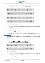
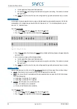
Both parameters are set with the same procedure. To set Phi and Theta:
1. Press and hold Num, then press Operate to set the unit into Off mode.
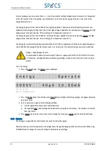
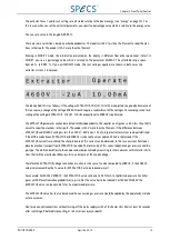
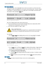
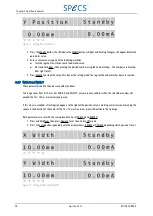
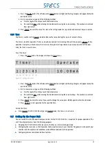
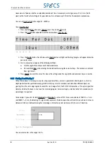
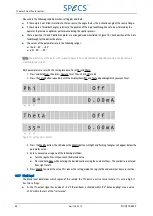
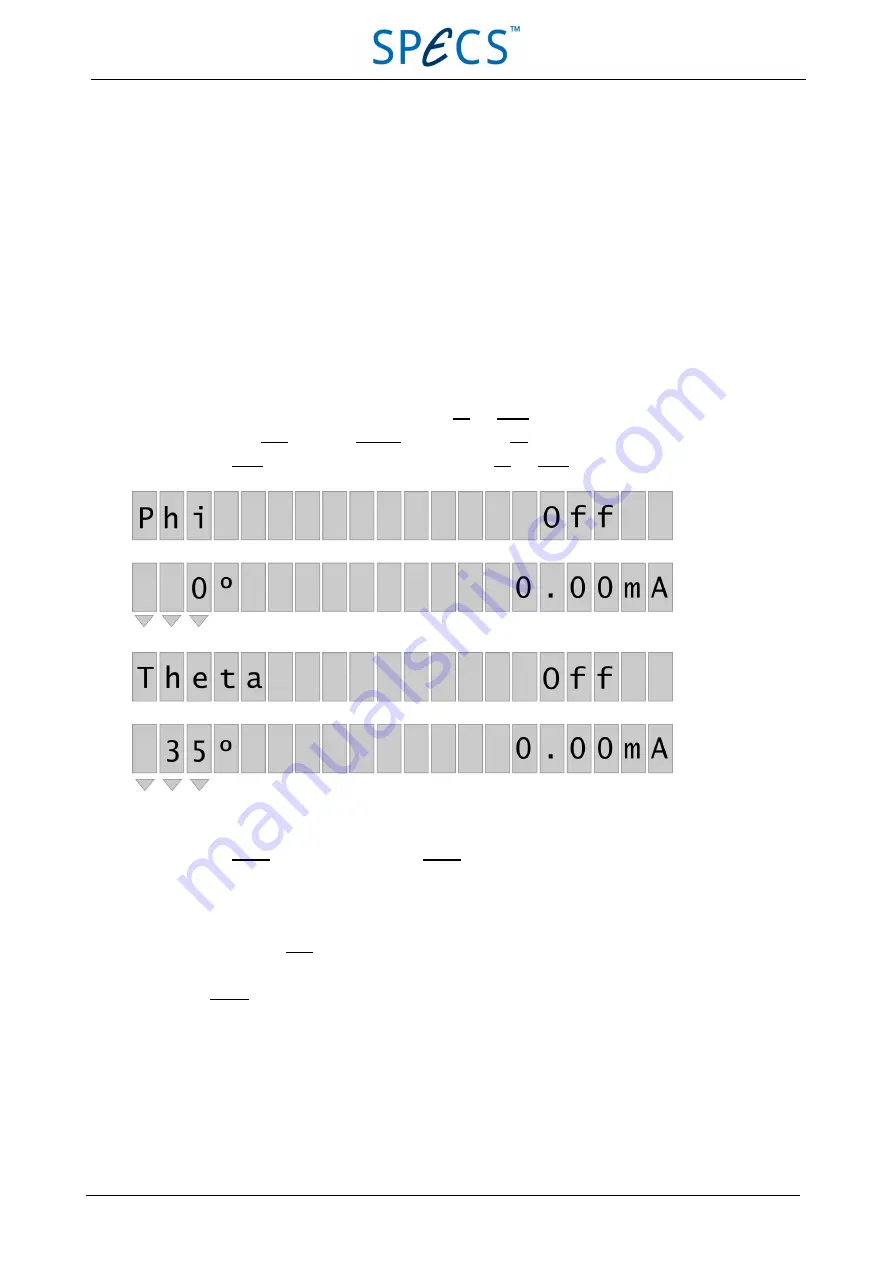
2. Press the Setup button repeatedly until the display showsPhi and Theta, depending which you want to set.
Figure 19: Setting phi and theta
3. Press the Modify button. The LED above the Modify button will light and flashing triangles will appear below the
parameter value.
4. Enter a new value using one of the following methods:
■
Turn the jog shuttle until you reach the desired value.
■
Press and hold Num while entering the desired number using the numerical keys. The numbers are entered
from right to left.
5. Press Modify to accept the value. This leaves the setting mode; the jog shuttle and numerical keys are inactive.
3.5.7 Blank Level
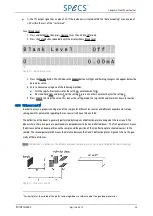
The blank level determines which region of the sample the TTL pulse is active low or where it is active high. It
has two settings:
■
0—the TTL output signal has a value of +5 V if the ion beam is situated within the “data accepting” area a value
of 0 V within the rest of the “raster area”.
24
April 26, 2013
PU IQE 12/383.0
Chapter 3 Front Panel Control

