Chapter 3 Front Panel Control
■
1—the TTL output signal has a value of 0 V if the ion beam is situated within the “data accepting” area a value of
+5 V within the rest of the “raster area”.
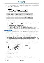
To set Blank Level:
1. Press and hold Num, then press Operate to set the unit into Off mode.
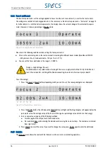
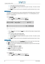
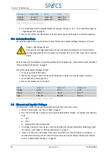
2. Press the Setup button repeatedly until the display shows Blank Level.
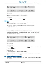
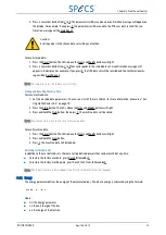
Figure 20: setting Blank Level
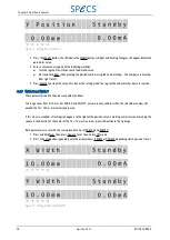
3. Press the Modify button. The LED above the Modify button will light and flashing triangles will appear below the
parameter value.
4. Enter a new value using one of the following methods:
■
Turn the jog shuttle clockwise for the setting 1; anticlockwise for 0.
■
Press and hold Num and press 0 for the setting 0; press any other numerical key for the setting 1.
5. Press Modify to accept the value. This leaves the setting mode; the jog shuttle and numerical keys are inactive.
3.5.8 Distances L and M
In order to ensure a proper scanning area of the sample for different ion sources and different experimental setups,
some geometric parameters regarding the ion source itself have to be entered.
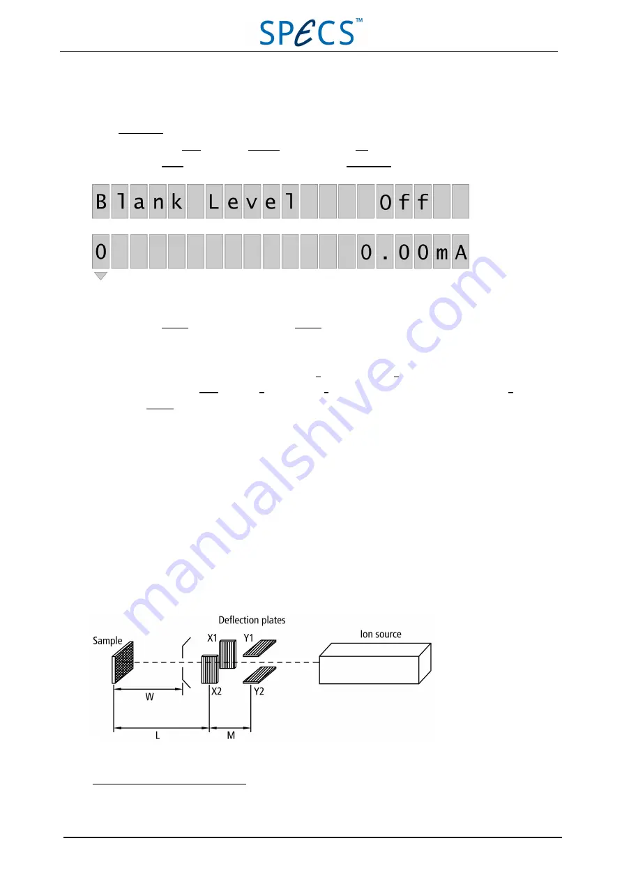
The deflection of the beam is generally performed by two pairs of deflection plates arranged at the source exit. The
planes where these two pairs are positioned are perpendicular to the non-deflected beam
1
. The first parameter L means
the distance between beam position on the sample and the position of the X deflection plate situated nearest to the
sample. The second parameter M means the distance between the X and Y deflection plates. Figure 21 shows the geo-
metry of these distances.
Note: The distance L is defined as the distance between sample to plates, not sample to top of the source housing.
Figure 21: Distances L and M
1
For short plates, the middle of the plates can be regarded as a reference point to a good approximation.
PU IQE 12/383.0
April 26, 2013
25

