background image

Chapter 6 Technical Description

PU IQE 12/383.0

April 26, 2013

45

Chapter 6

Technical Description

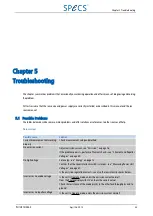
This chapter contains specifications and technical details about the PU IQE 12/38.

6.1 Pa cking List

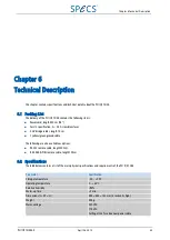
The delivery of the PU IQE 12/38 contains the following items:

Power cord, length 250 cm (98")

For US specification: 2 × 2.5 A slow blow fuses

2 HV bridge cables, length 10 cm

1 yellow/ green ground cable

The following are also available as options:

RS-232 remote cable, length 300 cm

IEEE-488 (GPIB) remote cable, length 100cm

6.2 Specif ica tions

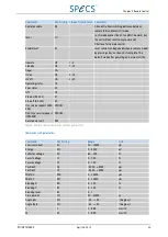
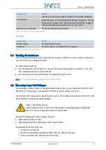
The table below contains a list of the main physical specifications and requirements of the PU IQE 12/38.

Parameter

Specification

Storage temperature

50…+70ºC

Operating temperature

0…+45ºC

Relative humidity

<90%

Warm-up time

<1 min

Dimensions (L × W × H)

495 × 483 × 133 mm (3 rack units high)

Weight

20 kg

Mains voltage

230 VAC

115 VAC

Setting at the fuse box near power cable

Summary of Contents for PU IQE 12/38

Page 1: ...49 30 46 78 24 0 Fax 49 30 46 42 08 3 Email support specs com Web http www specs com ISO 9001 Certificate Innovation in Surface Spectroscopy and Microscopy Systems Customized Systems and Solutions Nan...

Page 2: ...ed No part of this manual may be reproduced without the prior permission of SPECS GmbH Other product and company names mentioned in this document may be the trademarks or registered trademarks of thei...

Page 3: ...g On 4 2 5 Switching Off 5 Chapter 3 Front Panel Control 7 3 1 Front Panel 7 3 2 Display 9 3 3 Operation Modes 9 3 3 1 Operate 9 3 3 2 Standby 10 3 3 3 Off 10 3 3 4 Degas 11 3 4 Viewing and Modifying...

Page 4: ...Possible Problems 35 5 2 Checking the Resistance 37 5 3 Measuring Power Unit Voltages 37 5 3 1 Energy 38 5 3 2 Extractor 38 5 3 3 Focus 1 39 5 3 4 Focus 2 39 5 3 5 Deflection X1 X2 Y1 Y2 39 5 3 6 Ano...

Page 5: ...gure 16 Blanking X and Y 22 Figure 17 Setting Blanking X and Blanking Y 23 Figure 18 Angles phi and theta 23 Figure 19 Setting phi and theta 24 Figure 20 setting Blank Level 25 Figure 21 Distances L a...

Page 6: ......

Page 7: ...nsity 36 Table 10 Troubleshooting intensity fluctuations 36 Table 11 Troubleshooting no degas operation 37 Table 12 Troubleshooting dark display 37 Table 13 Checking the deflection voltages 40 Table 1...

Page 8: ......

Page 9: ...source for the pro duction of an ion beam in a vacuum chamber The manual is divided into the following chapters Chapter 2 explains how to install the PU IQE 12 38 and outlines the basic operation proc...

Page 10: ...you should pay special attention to the hazards spe cifically associated with this instrument as described in this manual Danger High Voltages Present The PU IQE 12 38 is capable of delivering lethal...

Page 11: ...bserve during installation Note You can find a complete description of the rear panel of the PU IQE 12 38 and its connection cable in Con nections on page 47 To install the PU IQE 12 38 1 Fit the ion...

Page 12: ...gs have been saved in the internal memory You can recall the setting by pressing RECALL then the data set number To change the calibration deflection 1 Set the power supply to OFF mode This is the cas...

Page 13: ...tial operation Recall a user defined data set by pressing the Recall button and then pressing a number key from 1 to 9 Press the parameter name that is marked on the number keys to view the status of...

Page 14: ......

Page 15: ...he features on the front panel it explains the following elements of operation Operation modes Viewing parameters and modifying their values including storing values Setting up the basic configuration...

Page 16: ...when the Num key is active 8 This key has two functions Selects the PosY parameter Enters the number 8 when the Num key is active 9 This key has two functions Selects the Width Y parameter Enters the...

Page 17: ...es Operation mode Emission current Figure 2 Display of the PU IQE 12 38 3 3 Operation Modes The ion source runs in four modes which are used for different purposes Standby Degas Operate Off These mode...

Page 18: ...by mode If the PU IQE 12 38 is in Standby or Off mode none of the red lights on the front panel should be active Standby mode is activated under the following circumstances By pressing Operate while i...

Page 19: ...message appears in the display if the final emission current cannot be reached During the degas procedure operation is indicated by the red light above the Degas button and the word Degas appears in...

Page 20: ...parameters for the PU IQE 12 38 You can save one set of machine parameters Table 2 shows a summary of the parameters that make up user and machine data User data Machine data Parameter Factory setting...

Page 21: ...n Table 2 for more information please see Set ting Up the Power Unit on page 19 2 Press the Store button The LEDs above the Num and Modify buttons will light 3 Press and hold the Num button then press...

Page 22: ...re is optimized Danger High Voltages Present Do not disconnect cables without turning off the mains supply switch of the PU IQE 12 38 Wait at least 1 minute after switching off before disconnecting an...

Page 23: ...20 V more than the filament If the difference between EXTRACTOR and ENERGY voltage is less than 200 V 80 V and 120 V a larger extractor current can be established If the difference between EXTRACTOR a...

Page 24: ...y switch of the PU IQE 12 38 Wait at least 30 seconds after switching off before disconnecting to avoid risk of serious injury or death To set the energy 1 Press the Focus1 or Focus2 button depending...

Page 25: ...he numerical keys The numbers are entered from right to left 4 Press Modify to accept the value If you want to change the value press Modify again to enter the edit mode 3 4 6 Pos X and Pos Y These pa...

Page 26: ...the area scanned by the beam The range spans from 0 10 mm For Width X and Width Y values are only valid for which the selected area does not exceed the 10 10 mm maximum square area If this area is exc...

Page 27: ...ess the Modify button The LED above the Modify button will light and flashing triangles will appear below the parameter value 3 Enter a new value using one of the following methods Turn the jog shuttl...

Page 28: ...Modify button will light and flashing triangles will appear below the parameter value 4 Enter a new value using one of the following methods Turn the jog shuttle until you reach the desired value Pres...

Page 29: ...ON and Y MON Extern switches off the internal deflection generator module of the PU IQE 12 38 You can apply voltages to the X MON and Y MON sockets on the deflection generator module see Figure 34 An...

Page 30: ...mode the jog shuttle and numerical keys are inactive 3 5 5 Blanking X and Blanking Y When the ion beam is rastering an area for a longer period of time a crater is generated Collecting data in situ fo...

Page 31: ...o left 5 Press Modify to accept the value This leaves the setting mode the jog shuttle and numerical keys are inactive 3 5 6 Angles Phi and Theta When the beam rasters the sample area different curren...

Page 32: ...d Num then press Operate to set the unit into Off mode 2 Press the Setup button repeatedly until the display showsPhi and Theta depending which you want to set Figure 19 Setting phi and theta 3 Press...

Page 33: ...numerical keys are inactive 3 5 8 Distances L and M In order to ensure a proper scanning area of the sample for different ion sources and different experimental setups some geometric parameters regar...

Page 34: ...esired value Press and hold Num while entering the desired number using the numerical keys The numbers are entered from right to left 5 Press Modify to accept the value This leaves the setting mode th...

Page 35: ...rs are entered from right to left 5 Press Modify to accept the value This leaves the setting mode the jog shuttle and numerical keys are inactive 3 5 10 HPIB Address You can set the address used for t...

Page 36: ...f the following methods Turn the jog shuttle until you reach the desired value Press and hold Num while entering the desired number using the numerical keys The numbers are entered from right to left...

Page 37: ...etting is 1200 You can change this according to your configuration To change the baud rate Press and hold Num then press Operate to set the unit into Off mode 2 Press the Setup button repeatedly until...

Page 38: ......

Page 39: ...interface is active the PU IQE 12 38 operates in slave mode Front panel buttons are inactive and a small green LED above the jog shuttle is lit If you have further questions regarding initial activati...

Page 40: ...mediately leads to a service request 4 1 3 CAN For details of how to use the CAN bus for remote control please contact SPECS support 4 2 Commands This section contains the commands that you can use fo...

Page 41: ...erating status OS Error status ES Off OF Echo on RS 232 E1 Echo off RS 232 E0 Use service request IEEE 488 SRQON Don t use service request IEEE 488 SRQOFF Reset power unit RES Table 4 Remote control c...

Page 42: ...e Range Current limit error CL B B T true or F false Cathode fail error VL B B T true or F false Regulation error RE B B T true or F false energy error EN B B T true or F false extractor error EX B B...

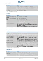
Page 43: ...ly Check measurement setup and method No emission current Adjust emission current see Emission on page 16 If the problem persists perform a filament check see Filament and Repeller Voltages on page 40...

Page 44: ...setup and method Dirty sample or insulating sample Clean the sample by sputtering for some minutes or replace the sample Unstable sputter gas pressure Check valves or replace gas cylinder Unstable em...

Page 45: ...hould show infinite resistance to other pins Resistance between the pins and the chamber This should be infinite in all cases Note The resistance may depend on temperature or applied voltage 5 3 Measu...

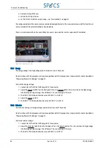
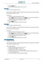
Page 46: ...Adjust the Energy to 5000 V on the front panel Press the Operate button This will switch on the high voltage the flashing warning message check filament has no meaning in this case 3 The DVM 1 1000 s...

Page 47: ...described in Measuring Power Unit Voltages on page 37 To check Focus 2 1 Connect the HVP with the DVM range 20 V to connector 2 Adjust the Focus 2 to 5000 V on the front panel Press the Operate butto...

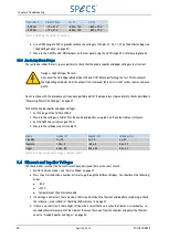
Page 48: ...0 V 2 Measure the voltages in Table 14 for the anode and repeller using pin 3 on the output cable as reference 3 Set the DVM to a current range of 20 A 4 Measure the cathode currents in Table 14 Mode...

Page 49: ...hat you understand the reason why the fuse blew in the first place Note Make sure that you are operating the PU IQE 12 38 according to the procedures described in Basic Oper ation on page 3 If Degas m...

Page 50: ...tor Module not found Scan Power If all modules are in the corresponding slots a serious error is probable Please contact SPECS I2C error Displayed if a fatal communication error in the PU IQE 12 38 oc...

Page 51: ...ter is set out of range The range depends on the energy of the ions If a certain area is selected while running at low energy the box can appear when the energy is increased See The flashing arrow on...

Page 52: ......

Page 53: ...ables length 10 cm 1 yellow green ground cable The following are also available as options RS 232 remote cable length 300 cm IEEE 488 GPIB remote cable length 100cm 6 2 Specifications The table below...

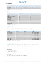
Page 54: ...0 25 V pp 10 s Repeller 80 V 1 mA 5 V 1 V pp 1 s Anode 120 V 10 mA 5 V 1 V pp 1 s Degas 560 V 15 mA 50 V 50 V pp 1 s Standby 12 V 4 0 A 1 V pp Filament 12 Vc 5 5 A 1 V pp Emission 15 mAd 5 1 min Ener...

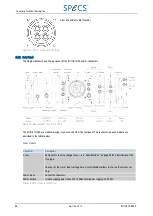
Page 55: ...on the output cable 6 4 1 High Voltage Cable There are two shielded single line high voltage cables for the focus voltages and by two special plugs The pin assign ment of these two plugs is shown bel...

Page 56: ...each module are described in the tables below Mains module Connector Description Fuses Remove this cover to change fuses see Specifications on page 45 for a description of the fuse type You can set t...

Page 57: ...r the deflection voltages e g to synchronize the scanning with other equipment The output is 0 10 V Y deflection monitor TTL blanking TTL output signal for blanking see Blank Level on page 24 Table 20...

Page 58: ...bus Male and female connectors for CAN bus remote control Energy monitor BNC connector providing a monitor forthe energy voltage 0 10 V on the monitor represents 0 5000 V energy voltage TTL HV On Off...

Page 59: ...dule 48 Degas Mode 11 40 New cathode 4 Replace fuse 41 Specifications 46 Display 9 Distance L M 25 DS100 28 E Emission 16 Energy 13 38 Specifications 46 Energy Monitor 50 Errors 42 Extractor 14 F Fila...

Page 60: ...t 47 Position X 17 Position Y 17 R Rear Panel 48 Recall 12 Remote Control 31 Commands 32 Remote Mode 28 Repeller 40 46 Resistance 37 Ripple 46 RS 232 31 S Safety 2 Scan Mode 21 Service Mode 41 Settle...

Reviews: