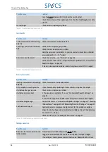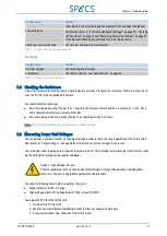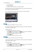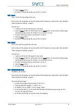
Connector
Description
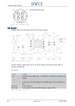
HV output 2
Labeled OUT2—this needs to be connected to IN2 on the emission regulation module.
Table 22: HV module connectors
HV module 2
The connectors on HV module 2 provide high voltage supplies to focus electrodes on the source.
Connector
Description
HV output
Labeled OUT1—this needs to be connected to Focus 1 on the source.
Not used
Labeled OUT2—this needs to be connected to Focus 2 on the source.
Table 23: HV module connectors
Main CPU module
Connector
Description
CAN-bus
Male and female connectors for CAN-bus remote control.
Energy monitor
BNC connector providing a monitor forthe energy voltage:
■
0–10 V on the monitor represents 0–5000 V energy voltage.
TTL HV On/ Off
BNC connector for controlling the HV status. See "Remote Mode" on page 28.
RS-232
Connector for RS-232 remote control.
IEEE-488
Connector for IEEE-488 remote control.
Table 24: Main CPU module connectors
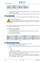
Note: See also "Remote Control" on page 31 for more information about the remote control connections.
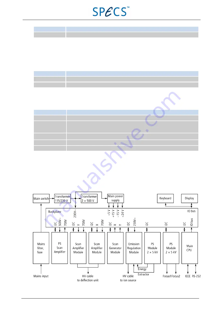
6.5 E lectronic Block Dia gra m
A diagram of the working principle of the PU IQE 12/38 is shown below.
Figure 35: Electronic block diagram
50
April 26, 2013
PU IQE 12/383.0
Chapter 6 Technical Description

