Chapter 3 Front Panel Control
To change I
Standby
:
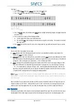
1. Press and hold Num, then press Operate to set the unit into Off mode.
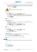
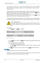
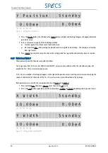
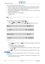
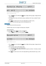
2. Press the Setup button repeatedly until the display shows I Standby.
Figure 15: Setting I
Standby
3. Press the Modify button. The LED above the Modify button will light and flashing triangles will appear below the
parameter value.
4. Enter a new value using one of the following methods:
■
Turn the jog shuttle until you reach the desired value.
■
Press and hold Num while entering the desired number using the numerical keys. The numbers are entered
from right to left.
5. Press Modify to accept the value. This leaves the setting mode; the jog shuttle and numerical keys are inactive.
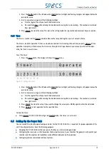
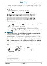
3.5.3 Scan Mode
You can select from three options for scan mode:
■
Intern operates the PU IQE 12/38 completely with its internal scan and deflection abilities as described in this
manual. The Intern scan mode is factory set.
■
Intern Out operates the PU IQE 12/38 with the same abilities as for the Intern selection, but additionally the X-MON
and Y-MON sockets on the deflection generator module (see Figure 34) are used as monitor outputs. The deflection
voltage of +/- 650 V at the plates are converted to +/- 10 V at X-MON and Y-MON.
■
Extern switches off the internal deflection generator module of the PU IQE 12/38. You can apply voltages to the X-
MON and Y-MON sockets on the deflection generator module (see Figure 34). An external voltage in the range
−
10…+10 V corresponds to a voltage in the range
−
650…+650 V applied to the deflection plates. With this con-
figuration, analog scan and deflection units can operate the deflection amplifiers of the PU IQE 12/38. This feature
is important when scanning the beam for imaging and mapping purposes.
Note: If Extern is selected for the scan mode, all settings for digital beam guidance by PU IQE 12/38 are switched off or
have no effect, i.e. Time Per Dot, Blanking X and Y, Angles Phi and Theta, Distances L and M, Deflection Sensitivities X
and Y, Blank Level.
Bear in mind that the scan mode can be selected in a different manner for different channels 0-9. In general, a part of
channels could be run with “Intern”, other could be run with “Extern” selection. For users running external scan and
deflection units for all their applications, the scan mode selection needs to be set to Extern mode for all channels.
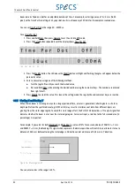
3.5.4 Time Per Dot
During rastering, the beam at the sample is aimed at grid points spaced 100
μ
m apart. The raster line distance can only
be independent of the incident angle or sample rotation when the geometric parameters are adjusted properly. The
PU IQE 12/383.0
April 26, 2013
21

