beam remains fixed on a dot for an adjustable duration of time. For example, rastering an area of 4 × 4 mm (1600
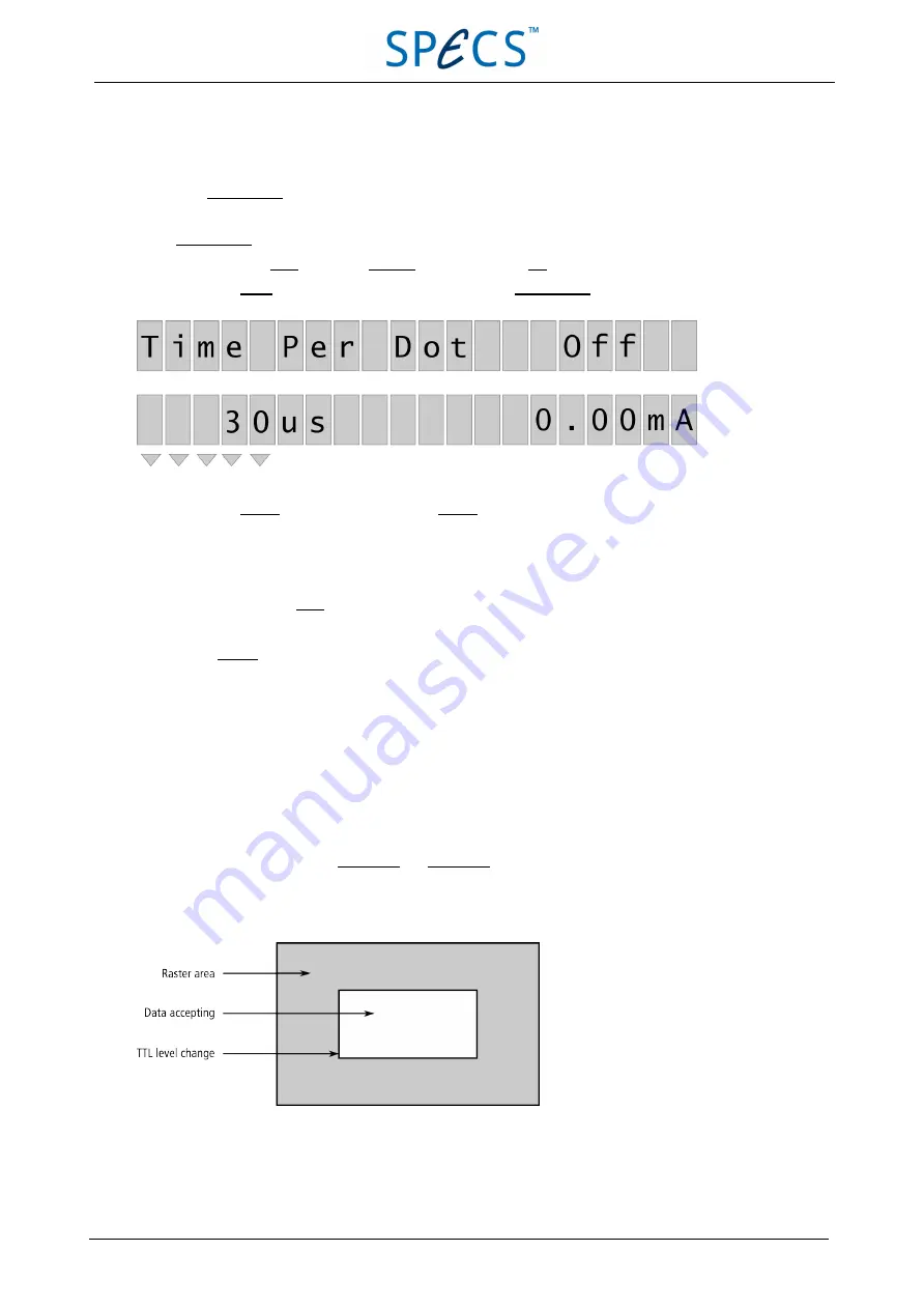
pixel) with a Time Per Dot setting of 30
μ
s per dot results in a frequency of 20.8 Hz for the complete scanned area.
You can set Time Per Dot in the range 30…30000
μ
s.
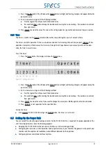
To set Time Per Dot:
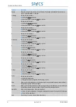
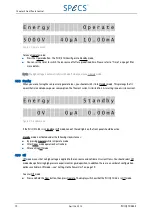
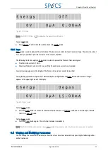
1. Press and hold Num, then press Operate to set the unit into Off mode.
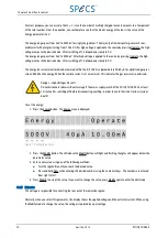
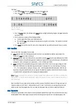
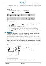
2. Press the Setup button repeatedly until the display shows Time Per Dot.
3. Press the Modify button. The LED above the Modify button will light and flashing triangles will appear below the
parameter value.
4. Enter a new value using one of the following methods:
■
Turn the jog shuttle until you reach the desired value.
■
Press and hold Num while entering the desired number using the numerical keys. The numbers are entered
from right to left.
5. Press Modify to accept the value. This leaves the setting mode; the jog shuttle and numerical keys are inactive.
3.5.5 Blanking X and Blanking Y
When the ion beam is rastering an area for a longer period of time, a crater is generated. Collecting data in-situ for a
depth profile from the sputtered area (e.g. SIMS or ISS) may result in interference of data from different layers ori-
ginating from the crater edge region. To avoid this crater edge effect, the PU IQE 12/38 provides a TTL output signal that
indicates whether the beam is at or near the crater edge region. For correct input, a relation to the full scanned area (in
percentage) is requested.
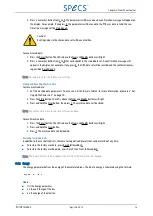
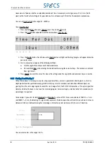
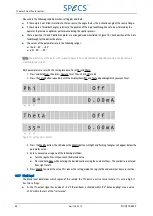
For example, if you select for both Blanking X and Blanking Y a value of 10% for an scanned area of Width X = 7 mm
and Width Y = 5 mm, the blanking TTL signal which represents the data acquisition will switch to an alternate state at a
distance of 0.35 mm before attaining the crater edge in X direction and at a distance of 0.25 mm in Y direction.
Figure 16: Blanking X and Y
You can enter values in the range 1–30%.
22
April 26, 2013
PU IQE 12/383.0
Chapter 3 Front Panel Control

