Chapter 3 Front Panel Control
Both parameters are set with the same procedure. To set Blanking X and Blanking Y:
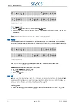
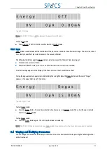
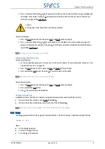
1. Press and hold Num, then press Operate to set the unit into Off mode.
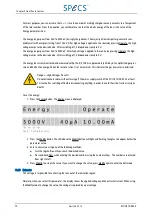
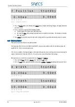
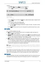
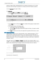
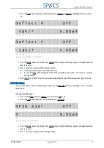
2. Press the Setup button repeatedly until the display shows Blanking X or Blanking Y, depending which you want
to set.
Figure 17: Setting Blanking X and Blanking Y
3. Press the Modify button. The LED above the Modify button will light and flashing triangles will appear below the
parameter value.
4. Enter a new value using one of the following methods:
■
Turn the jog shuttle until you reach the desired value.
■
Press and hold Num while entering the desired number using the numerical keys. The numbers are entered
from right to left.
5. Press Modify to accept the value. This leaves the setting mode; the jog shuttle and numerical keys are inactive.
3.5.6 Angles Phi and Theta
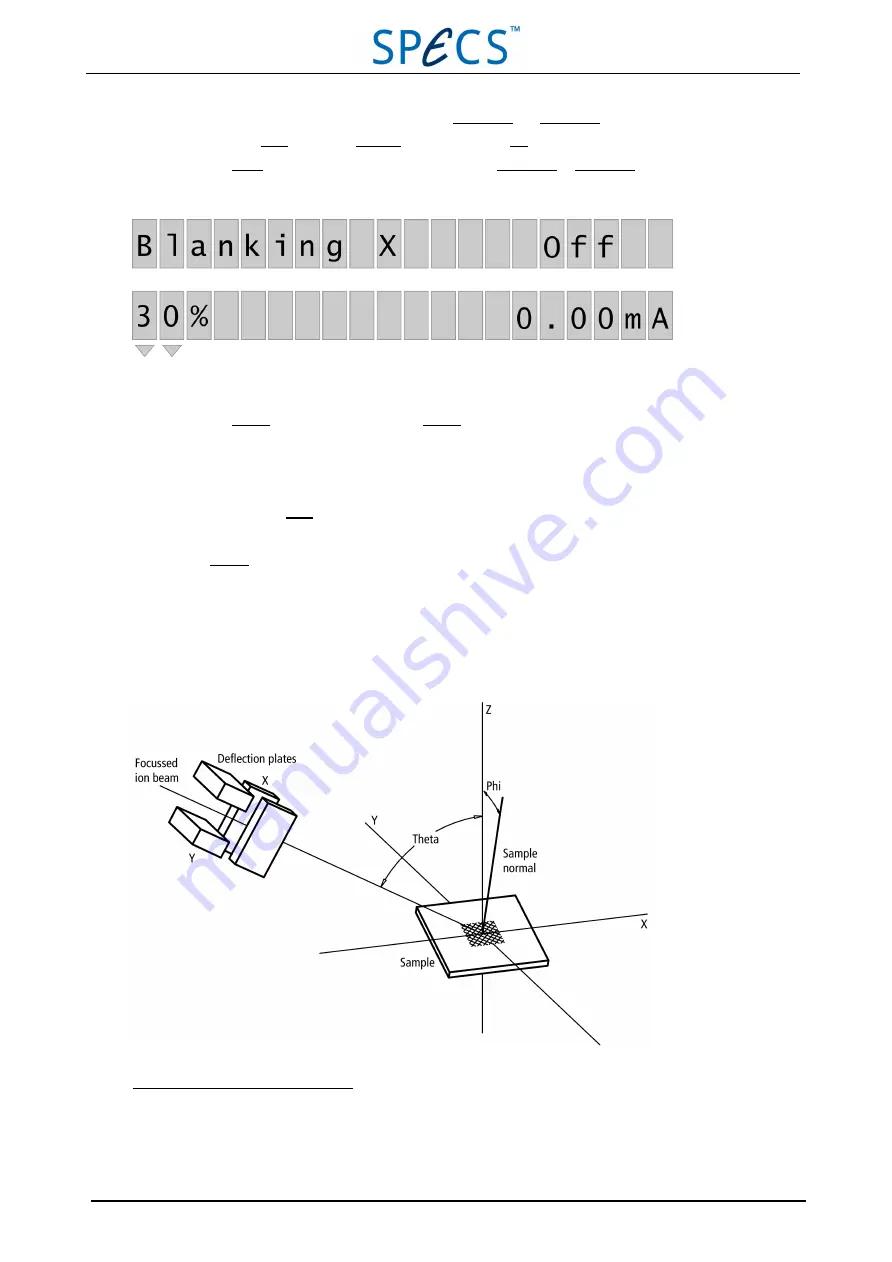
When the beam rasters the sample area, different current densities will usually sputter the sample depending on the
angle of incidence
1
. In order to reduce uneven erosion, the beam controlled by the PU IQE 12/38 repeatedly rasters on
equidistant points of a grid. This effect can only be achieved if the variation of the deflection angle to step the beam
from one grid point to the next depends on the position of the beam within the scanned area.
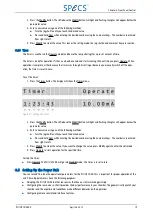
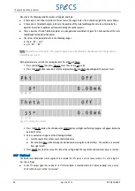
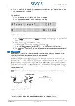
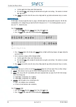
Figure 18: Angles phi and theta
1
The physical background is explained for example in U. Kaiser et al, "SIMS V", ed. A. Benninghoven et al., Springer Verlag,
Berlin Heidelberg New York Tokio (1986), p. 232 and B. Bilger, J. E. Fischer, "SIMS VII", ed. A. Benninghoven et al., John Wiley
& Sons, (1990), p. 639.
PU IQE 12/383.0
April 26, 2013
23


