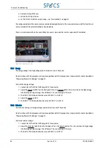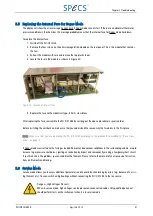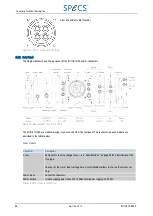
4. Remove the top of the case.
5. Switch the PU IQE 12/38 on.
6. Set the PU IQE 12/38 into service mode—see "Service Mode" on page 41.
The voltages adjusted at the source are measured and displayed internally. The measured values can differ from the val-
ues measured with the external method as described here.
There is an interlock switch on the cover. When the cover is removed, the switch is open and HV is disabled.
Figure 29: Interlock switch
5.3.1 Energy
The energy voltage is the high voltage used to accelerate ions in the source.
Do not continue with this procedure until you have performed all of the preparatory steps and safety checks described in
"Measuring Power Unit Voltages" on page 37.
To check the energy voltage:
1. Connect the HVP with the DVM (range 20 V) to connector .
2. Adjust the Energy to 5000 V on the front panel. Press the Operate button. This will switch on the high voltage
(the flashing warning message “check filament” has no meaning in this case).
3. The DVM (1:1000) should show the value of 5.000 V (± 0.001 V).
4. Adjust the Energy to 100 V.
5. The DVM (1 : 1000) should show the value of 0.100 V (± 0.001 V).
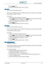
5.3.2 Extractor
The extractor voltage is the high voltage used to extract ions out of the source.
Do not continue with this procedure until you have performed all of the preparatory steps and safety checks described in
"Measuring Power Unit Voltages" on page 37.
To check extractor voltage:
1. Connect the HVP with the DVM (range 20 V) to connector .
2. Adjust the Extractor to 5000 V on the front panel. Press the Operate button. This will switch on the high voltage
(the flashing warning message “check filament” has no meaning in this case).
3. The DVM (1:1000) should show the value of 5.000 V (± 0.001 V).
38
April 26, 2013
PU IQE 12/383.0
Chapter 5 Troubleshooting

