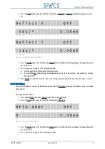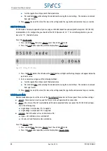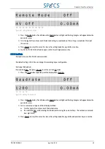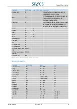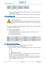
Pos X/ Pos Y
X Mon/ Y Mon
X1/ Y1
X2/ Y2
−
5.00 mm
−
10 ± 0.1 V
−
650 ± 10 V
+650 ± 10 V
+5.00 mm
+10 ± 0.1 V
+650 ± 10 V
−
650 ± 10 V
Table 13: Checking the deflection voltages
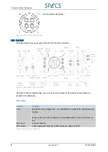
6. Use a DVM (range 1000V, to ground) to check the voltages at the pins X1, X2, Y1, Y2 on the deflector plug (see
"High Voltage Cable" on page 47).
7. Measure the X-MON and Y-MON outputs on the rear panel using the DVM (range 20 V, reference to ground).
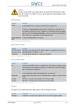
5.3.6 Anode, Repeller and Degas
This section describes the tests you can perform to check that the anode, repeller and degas voltages are all correct.
Danger—High Voltages Present!
Disconnect the HV bridge cable between IN1 and OUT1 before performing this test. This disconnects
the high voltage modules from the output! If not removed, there exists risk of serious injuries and even
death.
Do not continue with this procedure until you have performed all of the preparatory steps and safety checks described in
"Measuring Power Unit Voltages" on page 37.
To check the anode, repeller and degas voltages:
1. Set the range of the DVM to 1000 V.
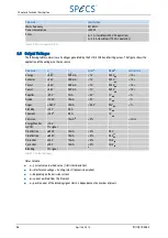
2. Measure the voltages in Table 14 for the anode and repeller, using pin 3 on the output cable as reference.
3. Set the DVM to a current range of 20 A.
4. Measure the cathode currents in Table 14
Mode
Anode (V)
Repeller (V)
Cathodes (A)
Standby
0 ± 10
0 ± 10
3 ± 0.1
Operate
120 ± 5
−
80 ± 5
5.5 ± 0.1
Degas
600 ± 50
600 ± 50
5.5 ± 0.1
Table 14: Anode and repeller voltages, cathode current
5.4 Fila ment a nd Repeller Volta ges
This check makes sure that the filament is working correctly and there are no short circuits:
1. Switch to Service mode—see "Service Mode" on page 41.
2. Press the emission button a number or times to go through the different displays. You should see the following
values:
■
−
80 V
■
+120 V
■
Temperature of the emission module
3. If a voltage is not correct, there may be a short circuit between the filament and repeller or anode cage. Check
the resitances, as described in "Checking the Resistance" on page 37.
4. If there is no short circuit, there might still be a short circuit that occurs when the filament is switched on, i.e.
caused by thermal movement of the filament. Remove the source from the chamber and adjust the filament.
See also "Anode, Repeller and Degas" on page 40.
40
April 26, 2013
PU IQE 12/383.0
Chapter 5 Troubleshooting


