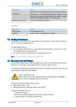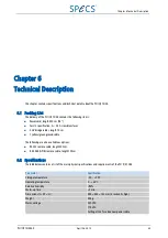
Parameter
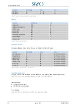
Specification
Mains frequency
50 / 60 Hz
Power consumption
<250 W
Fuses
2 × 1 A slow blow (230 VAC operation)
2 × 2.5 A slow blow (115 VAC operation)
Table 16: Physical specifications
6.3 Output Volta ges
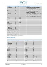
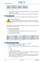
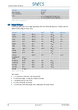
The following table summarizes all voltages generated by the PU IQE 12/38 and limiting values. The figure shows the
application of the voltages to the ion source.
Parameter
U
max
I
max
Error
a
Ripple
b
Settle time
Energy
+5 kV
0.49 mA
<1 V
0.25 V
pp
<10 s
Extractor
+5 kV
0.49 mA
<1 V
0.25 V
pp
<10 s
Focus1
+5 kV
0.49 mA
<1 V
0.25 V
pp
<10 s
Focus2
+5 kV
0.49 mA
<1 V
0.25 V
pp
<10 s
Repeller
−
80 V
1 mA
<5 V
1 V
pp
<1 s
Anode
+120 V
10 mA
<5 V
1 V
pp
<1 s
Degas
+ 560 V
15 mA
<50 V
50 V
pp
<1 s
Standby
+12 V
4.0 A
-
1 V
pp
-
Filament
+12 V
c
5.5 A
-
1 V
pp
-
Emission
-
15 mA
d
<5%
-
<1 min
Energy Monitor
+10 V
-
-
-
-
HV ON
TTL signal
-
-
-
-
X-deflection
±650 V
15 mA
<5%
0.5 V
pp
-
Y-deflection
±650 V
15 mA
<5%
0.5 V
pp
-
X-monitor
±10 V
10 mA
<5%
7 mV
pp
-
Y-monitor
±10 V
10 mA
<5%
7 mV
pp
-
Blanking
TTL signal
-
e
-
-
Table 17: Output voltages
Notes to table:
■
a—| actual value- desired value | (statistical deviation)
■
b—interference v hunting (elect.) (dynamic deviation)
■
c—depending on the emission current
■
d—current emitted from the filament
■
e—position error of the blanking signal which is dependent on the number of pixels
46
April 26, 2013
PU IQE 12/383.0
Chapter 6 Technical Description


