Chapter 6 Technical Description
Caution!
Do not use the mains output for any purpose other than to drive the PS-WF Wien filter power supply.
The current is limited to 1 A and there is no fuse—using the connection for any other purpose may des-
troy the PU IQE 12/38.
Deflection amplifier
Connector
Description
Ground
Connected directly to the case of the unit. Connect this to a common earth.
For best results, A grounding bar (copper, brass) with a minimum cross section of 6 mm x 6
mm should be installed inside the rack. All electronic units should be connected to this ground-
ing bar by means of flat braided grounding ribbons, which are connected to the back panels of
the electronic units. This helps reduce the effect of electrical noise.
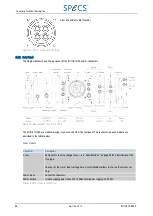
Output to deflection
plates
Connect to the deflection plates on the source.
Table 19: Deflection amplifier connections
Deflection generator module
Connector
Description
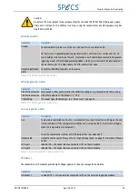
X deflection monitor These outputs allow you to monitor the deflection voltages, e.g. to synchronize the scanning
with other equipment. The output is 0…10 V.
Y deflection monitor
TTL blanking
TTL output signal for blanking—see "Blank Level" on page 24.
Table 20: Deflection generator connections
Emission regulation module
Connector
Description
Fan
Temperature controlled fan. The fan is switched on for a short time after switching on the unit.
It also switches on if the temperature inside the unit rises above 65ºC; it will switch off again
when the temperature falls below 45ºC.
The unit automatically switches off if the temperature rises above 85ºC.
Output cable
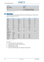
Output to the ion source. Please refer to "High Voltage Cable" on page 47 or details of the con-
nector.
HV input 1
Labeled IN1—this needs to be connected to OUT1 on the HV module.
HV input 2
Labeled IN2—this needs to be connected to OUT2 on the HV module.
Table 21: Emission regulation module connections
HV module 1
The connectors on HV module 1 provide high voltage supplies to the emission regulation module.
Connector
Description
HV output 1
Labeled OUT1—this needs to be connected to IN1 on the emission regulation module.
PU IQE 12/383.0
April 26, 2013
49

