9
XR 50
V3.1 | May 02, 2016
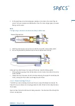
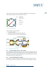
2. Fit the water hoses onto the cooling pipes, making sure to observe the correct flow dir-
ection. The hoses and pipes are labeled with arrows. The center (longer) pipe is for water
flowing into the source.
Note
The high voltage connections are also made when you fit the hoses.
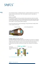
3. Slide the protection cap over the frame so that the contact fits into the safety switch.
4. Secure the protection cap with the three screws around the side of the cap.
Removing the protection cap is the reverse of the above. Note the following points:
When pulling the cap away from the head, take care not to strain the cable for the safety
switch interlock.
Always disconnect the water connectors before removing the support frame. Without the
frame, the weight of the conduit can damage the water hoses.
2.4.2
Head Cooling Circuit
The XR 50 has a second cooling circuit to cool the area around the filament and anode. The
body of the source remains cool, reducing radiative transfer of heat to other components (or
the sample).
Figure 3 shows the location of the head cooling connectors. The direction of flow through this
circuit is not important.
Summary of Contents for XR 50
Page 1: ...XR 50 XR 50 NAP X Ray Source User Manual V3 1 May 02 2016...
Page 6: ...XR 50 V3 1 May 02 2016 This page intentionally left vi...
Page 20: ...XR 50 V3 1 May 02 2016 This page intentionally left 14...
Page 30: ...XR 50 V3 1 May 02 2016 This page intentionally left 24...
Page 38: ...XR 50 V3 1 May 02 2016 This page intentionally left 32...
Page 46: ...XR 50 V3 1 May 02 2016 This page intentionally left 40...
Page 58: ......

