background image

XR 50

V3.1 | May 02, 2016

Three operating parameters are also shown in the display. You can view others by pressing the

and

keys to scroll the display. The complete list of parameters available in the display is:

Ÿ

Anode Voltage

Ÿ

Emission Current

Ÿ

Anode Current

Ÿ

Filament Voltage

Ÿ

Filament Current

There are the following active softkeys in the operating menu:

Ÿ

Menu—opens the main menu. This is the same as the initial menu but without the options

for conditioning the filament. You can view and change all settings from this menu.

Ÿ

Presets—opens the presets menu, allowing you to select a different preset.

3.3

Switching Off the Source

To switch off the source:

Ÿ

Press the

Standby

button on the front panel. This switches the high voltage off and sets the

filament to its standby value. The water cooling is still on in this case.

Ÿ

Press the

Shutdown

button. This switches the high voltage, the filament and the water sup-

ply off.

18

Summary of Contents for XR 50

Page 1: ...XR 50 XR 50 NAP X Ray Source User Manual V3 1 May 02 2016...

Page 2: ...l XR 50 X Ray Source Version 3 1 May 02 2016 SPECS order number reference 2100002828 2016 All rights reserved No part of this manual may be reproduced without the prior per mission of SPECS GmbH Other...

Page 3: ...Head Cooling Circuit 9 2 5 Connecting Electrical Supplies 10 2 5 1 Electrical Connections 10 2 5 2 Interlocks 11 2 6 Anode and Filament Conditioning 12 Chapter 3 Operation 3 1 Switching On 15 3 2 Adju...

Page 4: ...Cathode 38 6 2 3 Operation Range 38 6 2 4 Setup 39 Chapter 7 Principles of Operation 7 1 Generation of X Rays 41 7 2 Output Intensity 41 7 3 Voltages and Currents 42 7 3 1 Anode Voltage and Current 4...

Page 5: ...hrough 21 Figure 13 Checking isolation of sections in the source 21 Figure 14 Correct orientation of anode 22 Figure 15 Distance of anode to cross talk suppression ring 22 Figure 16 Setting the cap po...

Page 6: ...XR 50 V3 1 May 02 2016 This page intentionally left vi...

Page 7: ...e procedures that you can perform on the source Chapter 6 is an overview of the construction of the source including specifications Chapter 7 offers some background information about the principle of...

Page 8: ...specially insulated tools rated for voltages higher than 20 kV The XR 50 module uses high voltages up to 15 kV It is important to comply with the following safety directives Use only original cables...

Page 9: ...In addition to the regulations restrictions codes and rules for protection against radiation which have to be observed by the law at the operational site of the XR 50 SPECS recommends the following A...

Page 10: ...XR 50 V3 1 May 02 2016 800 1200 mbar Air conditioning is advisable in order to ensure the ambient requirements especially for dis sipating heat produced by the equipment 4...

Page 11: ...nuing 2 2 Vacuum Installation The XR 50 is suitable for UHV chambers and is mounted on a DN40CF flange When installing the XR 50 check the following The inner diameter of the flange where the XR 50 wi...

Page 12: ...n your configuration you may also want to fit a valve to the bypass line in order to be able to isolate the differential pumping section from the pumping chamber More elaborate bypass systems include...

Page 13: ...een the HV shield and the Z drive a spacer is provided This is a 40 mm tube with a DN40CF flange at each end one flange being rotatable You should attach the items to the chamber in the following orde...

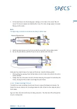
Page 14: ...to the stable and reliable operation of the XR 50 Please refer to the CCX 70 manual for requirements of the cool ing water 2 4 1 Fitting the Protection Cap During operation the top flange of the XR 5...

Page 15: ...oving the protection cap is the reverse of the above Note the following points When pulling the cap away from the head take care not to strain the cable for the safety switch interlock Always disconne...

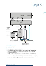
Page 16: ...l as well as the water connections for the XR 50 If you have a water chiller supplied by SPECS you can set it so that is it automatically switched on and off by the CCX 70 There are two alternative me...

Page 17: ...sending the signal to the UXC 1000 If these parameters fall outside the limits set in the UXC 1000 source operation is stopped HV the HV cable must be plugged into the back of the UXC 1000 before the...

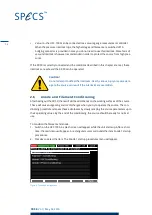
Page 18: ...the source can result if the interlocks are overridden 2 6 Anode and Filament Conditioning After baking out the XR 50 there will still be adsorbates on the working surfaces of the source These will c...

Page 19: ...as finished a notification will appear 8 Press OK The screen will return to the Anode 1 startup procedures menu Note Since the two anodes are electrically connected this procedure also conditions anod...

Page 20: ...XR 50 V3 1 May 02 2016 This page intentionally left 14...

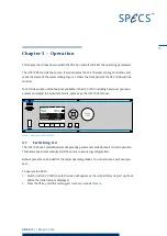
Page 21: ...set your own presets and adjust the instrument limits please see the UXC 1000 manual Figure 7 Front panel of the UXC 1000 3 1 Switching On The UXC 1000 uses predefined sets of operating parameters cal...

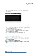
Page 22: ...to select the preset you want to use Figure 9 Selecting a preset 5 Press the key to select the preset A new screen appears which shows a list of para meters for the preset The center column shows the...

Page 23: ...e operating screen The filament current ramps up to the standby current The high voltage is ramped up to the value in the preset The filament current is ramped up until the emission current enables th...

Page 24: ...opens the main menu This is the same as the initial menu but without the options for conditioning the filament You can view and change all settings from this menu Presets opens the presets menu allowi...

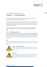
Page 25: ...of the XR 50 is high voltage spark ing There are a number of reasons for this If HV sparks occur the power supply will switch off the HV and go into standby mode At the beginning of operation and aft...

Page 26: ...pacing is especially critical It should be 3 2 mm Contamination or dust particles can cause HV sparks that result in the formation of small craters Note HV sparks outside the vacuum can affect the pre...

Page 27: ...4 pin feedthrough Figure 13 Checking isolation of sections in the source 4 3 Unstable Operation at Low Power At very low powers 5 W the emission may be erratic This is due to a limitation in the powe...

Page 28: ...hamber to check the orientation You can then easily correct the problem Figure 14 shows the front of the source without guard ring and aluminium window with the correct orientation of the anode Figure...

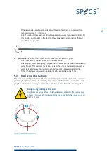
Page 29: ...016 To adjust the cap position Loosen the eight screws in the cap and slide the cap to the correct position You can then tighten the screws Figure 16 Setting the cap position Caution Do not damage the...

Page 30: ...XR 50 V3 1 May 02 2016 This page intentionally left 24...

Page 31: ...water inlet replacement or refurbishment if necessary and thorough testing with a specification report 5 1 X Ray Source Check If you remove the XR 50 for maintenance you should place the source on a f...

Page 32: ...ages Present It will take 3 minutes before all high voltages are absent in the system Wait at least 3 minutes before disconnecting any cables from the power supply or the X ray source Carry out the fo...

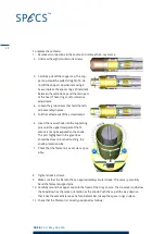
Page 33: ...his seal only needs to be water tight not a vacuum seal However a water leak will create a short circuit to ground causing the power supply to trip Tighten the screws until you can no longer see the g...

Page 34: ...e new cathode into the supporting pins until the uppermost part of the fil ament is not quite exposed to the anode The part highlighted in the green box should be close to but not touching the anode p...

Page 35: ...he filament is not deformed in its first use Note If you are using a filament from another manufacturer it may be necessary to adjust the standby current and current limit setting See the UXC 1000 man...

Page 36: ...e filament from entering the energy ana lyzer Additionally the X ray window acts as a barrier between the main chamber and anode volumes The Al window can be torn perforated or otherwise destroyed by...

Page 37: ...window lies flat on the cooling cap and is not bent 5 Screw the ring into place 5 6 Anode Storage When the source or the anode is stored in air for extended periods the surface of the anode can becom...

Page 38: ...XR 50 V3 1 May 02 2016 This page intentionally left 32...

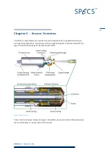
Page 39: ...ectron spec troscopy XPS experiments also known as electron spectroscopy for chemical analysis ESCA Figure 19 shows the major parts that make up the XR 50 Figure 19 Source overview Table 1 lists the f...

Page 40: ...ation energies enables a rapid distinction of Auger electron lines from photoelectron structures Normally the two active materials are aluminium and magnesium although a variety of other materials are...

Page 41: ...rmine the binding energies of core levels within 0 2 eV Low energy X ray excitation lines e g Zr M are attractive based on their energies of 132 eV and 151 eV and their natural line widths of 470 meV...

Page 42: ...2 K 5 17 6 0 6 20 1 0 4 K 6 20 6 0 5 23 4 0 3 K 48 7 0 5 69 7 0 6 Table 3 Mg Al K satellites 6 1 3 Cross Talk There is a small rod behind the Al window which reduces the cross talk between the excitat...

Page 43: ...ere are two cooling circuits in the XR 50 The anode cooling is shown in the cutaway picture in Figure 23 Two concentric axial tubes form the cooling circuit the inner delivers water directly to the an...

Page 44: ...are listed below Property Specification Material Al Mg other materials upon request Base material Ag tipped Voltage 15 kV max 0 40 mA with respect to ground Power dissipation 1 kW max Continuous load...

Page 45: ...ifications below describe the mechanical properties of the source Property Specification Vacuum pumping Via analysis chamber or via separate pumping line Outer jacket Copper pipes and copper blocks wa...

Page 46: ...XR 50 V3 1 May 02 2016 This page intentionally left 40...

Page 47: ...ls are ionized If these vacancies are refilled by electrons from energetically higher levels characteristic X ray radiation is generated Figure 25 Principle of operation In addition to this process Br...

Page 48: ...he operation of the XR 50 it has two constituents Emission current Water current 7 3 2 Emission Current During operation electrons are emitted from the filament and accelerated toward the anode An emi...

Page 49: ...uctivity as well as the length and thickness of the water hoses The water current is calculated in the UXC 1000 from the relation 1 I I I W A E The net power of the anode consists of X ray radiation a...

Page 50: ...necessary to have a small field in the volume between the anode sample and energy ana lyzer in order to produce X ray excited photoelectron lines of different kinetic energies from the same element i...

Page 51: ...orming a seal The sheath is welded to a flange When it is in place therefore the interior of the X ray source is isolated from the rest of the vacuum chamber There is a thin 0 2 m silicon nitride wind...

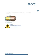
Page 52: ...en degassing the filament make sure that the cooling water is running This ensures that the sheath does not heat up and thereby prevents any damage to the Viton O ring Caution The silicone nitride win...

Page 53: ...t window from SPECS Conducting silver paint In case the anode needs to be cleaned 10 mm wrench spanner and new DN40CF gasket To replace the window 1 Remove the four screws at the source head 2 Remove...

Page 54: ...o place 6 Use a fine paintbrush to paint a thin strip of silver paint between the window and the source cap or source body The window has an aluminium coating to prevent the window from charging There...

Page 55: ...35 F Feedthrough 21 34 Filament See Cathode G Guard Ring 22 31 H Head Cooling 37 38 High Pressure 45 High Voltage 42 Hose Connectors 38 HV Sparks 19 I Interlock 34 L Line Widths 35 M Magnetic Fields...

Page 56: ...leshooting 19 W Water Current 43 Water Circulation 37 Water Cooling 8 Water Current 43 Water Inlet 29 Weight 39 Window 45 47 Working Distance 38 Working Pressure 39 X X Rays Excitation Energies 35 Gen...

Page 57: ...robiological substances incl sample material radioactive substances incl sample material ionizing particles radiation neutrons Is the equipment free from potentially harmful and hazardous substances 4...

Page 58: ......
Reviews: