v
XR 50
V3.1 | May 02, 2016
List of Figures
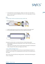
Figure 1: Differential pumping flange
Figure 2: Bypass ring in the open position
Figure 3: Head cooling connections
Figure 4: Electrical and water connections
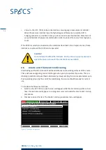
Figure 5: The source startup menu
Figure 6: Conditioning the filament
Figure 7: Front panel of the UXC 1000
Figure 8: Entering the presets menu
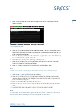
Figure 10: Activating a preset
Figure 12: Pins on filament feedthrough
Figure 13: Checking isolation of sections in the source
Figure 14: Correct orientation of anode
Figure 15: Distance of anode to cross-talk suppression ring
Figure 16: Setting the cap position
Figure 17: Cathode (filament) assembly
Figure 18: Anode water cooling flange and tube
Figure 20: Limits menu for setting maximum anode power
Figure 21: Cross-talk suppression
Figure 22: Cross-talk in the XR 50
Figure 23: Anode cooling circuit
Figure 24: Heat cooling circuit
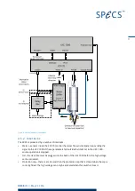
Figure 25: Principle of operation
Figure 26: The voltages and currents involved in the X-ray source
Summary of Contents for XR 50
Page 1: ...XR 50 XR 50 NAP X Ray Source User Manual V3 1 May 02 2016...
Page 6: ...XR 50 V3 1 May 02 2016 This page intentionally left vi...
Page 20: ...XR 50 V3 1 May 02 2016 This page intentionally left 14...
Page 30: ...XR 50 V3 1 May 02 2016 This page intentionally left 24...
Page 38: ...XR 50 V3 1 May 02 2016 This page intentionally left 32...
Page 46: ...XR 50 V3 1 May 02 2016 This page intentionally left 40...
Page 58: ......

