XR 50
V3.1 | May 02, 2016
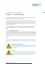
The following checks may help you locate the cause of the problem. Contact SPECS (sup-
port@specs.com) before performing potentially dangerous test procedures in your laboratory.
As a first step, check the following:
Water cooling. Make sure that the water temperature, flow and quality are all adequate.
See the CCX 70 manual for more information about the water requirements.
Anode power. Make sure it is within the limit set in "Operating Limits" on page 34.
Do the sp arks cause a p ressure b urst?
Do the sparks affect the pressure inside the vacuum chamber? If so, check the following:
Operating pressure (10
–6
mbar or lower).
Water conductivity (see "Water Current" on page 43).
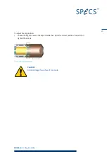
Aluminium window (see "Replacing the Aluminium Window" on page 30).
Anode condition (see "Replacing the Anode" on page 26)
Remove the source and check the following:
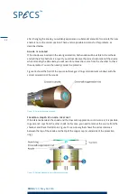
The distance between the anode and Al window rod. This rod suppresses the crosstalk
and the spacing is especially critical. It should be ~3.2 mm
Contamination or dust particles can cause HV sparks that result in the formation of
small craters.
Note
HV sparks outside the vacuum can affect the pressure reading—the response of the pressure
gauge controller to a HV discharge may look like a pressure burst.
Are the co nnectio ns and cab les intact?
Switch off the UXC 1000 and check the following:
The cables should all be intact, with no signs of wear or fraying. Remove the protection cap
and check the cable carefully.
Are there any traces of water, dirt or other contamination inside the protection cap? Check
also the flange, connectors and insulators.
Is the p o wer sup p ly wo rking co rrectly?
In the event of a problem with the power supply, the UXC 1000 will display an error message on
the display. Please refer to the UXC 1000 manual for a list of all error messages.
4.2
Basic Electrical Checks
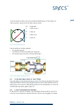
If the source is not working, you should first check that all parts are electrically intact. Use a
digital multimeter to perform the checks in this section in order to make sure there are no
short cuts and that the filament is not broken.
20
Summary of Contents for XR 50
Page 1: ...XR 50 XR 50 NAP X Ray Source User Manual V3 1 May 02 2016...
Page 6: ...XR 50 V3 1 May 02 2016 This page intentionally left vi...
Page 20: ...XR 50 V3 1 May 02 2016 This page intentionally left 14...
Page 30: ...XR 50 V3 1 May 02 2016 This page intentionally left 24...
Page 38: ...XR 50 V3 1 May 02 2016 This page intentionally left 32...
Page 46: ...XR 50 V3 1 May 02 2016 This page intentionally left 40...
Page 58: ......


