XR 50
V3.1 | May 02, 2016
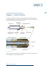
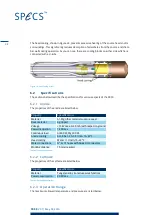
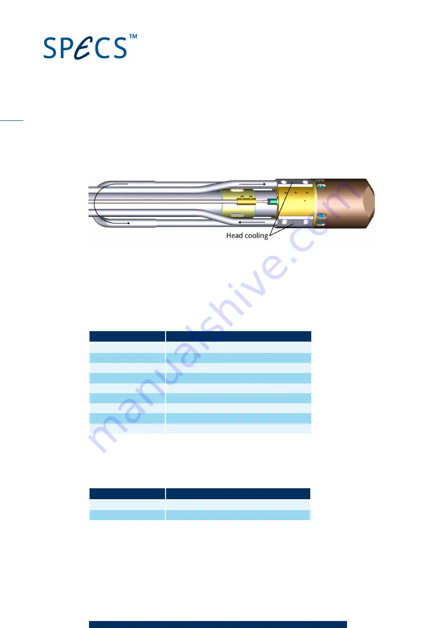
The head cooling, shown in Figure 24, prevents excessive heating of the source head and its
surroundings. This significantly reduces desorption of adsorbates from the source and cham-
ber walls during operation. As you can see, there are cooling blocks on either side which are
connected with a U-tube.
Figure 24: Heat cooling circuit
6.2
Specifications
The sections below describe the specifications for various aspects of the XR 50.
6.2.1
Anode
The properties of the anode are listed below.
Property
Specification
Material
Al, Mg; other materials upon request
Base material
Ag-tipped
Voltage
+15 kV max. 0–40 mA (with respect to ground)
Power dissipation
1 kW max.
Continuous load
Al 400 W, Mg 300 W.
Anode cooling
6 to 8 bar, 2.5–3.5 l/min, 15–22°C
Head cooling
Water > 1 l/min, 15–22°C
Water connections
¾" or ½" hoses with Quick Fit connectors
Working distance
15 mm (regular)
Table 4: Anode specifications
6.2.2
Cathode
The properties of the cathode are listed below.
Property
Specification
Material
Tungsten alloy (to reduce work function)
Power consumption
30 W max.
Table 5: Cathode specifications
6.2.3
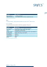
Operation Range
The maximum allowed temperature and pressure are listed below.
38
Summary of Contents for XR 50
Page 1: ...XR 50 XR 50 NAP X Ray Source User Manual V3 1 May 02 2016...
Page 6: ...XR 50 V3 1 May 02 2016 This page intentionally left vi...
Page 20: ...XR 50 V3 1 May 02 2016 This page intentionally left 14...
Page 30: ...XR 50 V3 1 May 02 2016 This page intentionally left 24...
Page 38: ...XR 50 V3 1 May 02 2016 This page intentionally left 32...
Page 46: ...XR 50 V3 1 May 02 2016 This page intentionally left 40...
Page 58: ......


