45
XR 50
V3.1 | May 02, 2016
Chapter A – XR 50 NAP
The XR 50 is also available as the XR 50 NAP. This is a version suitable for measurements in
near ambient pressures (up to 25 mbar).
This appendix provides a short overview of the XR 50 NAP, highlighting the features and oper-
ation modes where they differ from the standard XR 50.
A.1
Construction
The XR 50 NAP differs from the standard XR 50 in two ways:
The copper cap on the source head has a different design
The source is surrounded by a metal sheath.
A Viton O-ring is fitted around the copper cap. When the sheath is fitted, this presses against
the O-ring, forming a seal. The sheath is welded to a flange. When it is in place, therefore, the
interior of the X-ray source is isolated from the rest of the vacuum chamber.
There is a thin (0.2 μm) silicon nitride window mounted on the front end of the XR 50 NAP. This
allows the transmission of X-rays while providing a physical barrier between the source interior
and the high pressure in the chamber. The limit on the pressure difference between the
interior of the X-ray source and the measurement chamber is determined by the O-ring and the
window. The window is coated with aluminium on both sides to prevent charging during oper-
ation.
A turbopump needs to be fitted to the pumping port on the source.
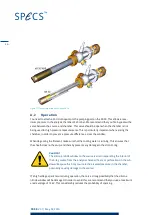
Figure 27 shows the XR 50 NAP and the XR 50. You can clearly see the sheath that isolates the
source from the chamber.
Summary of Contents for XR 50
Page 1: ...XR 50 XR 50 NAP X Ray Source User Manual V3 1 May 02 2016...
Page 6: ...XR 50 V3 1 May 02 2016 This page intentionally left vi...
Page 20: ...XR 50 V3 1 May 02 2016 This page intentionally left 14...
Page 30: ...XR 50 V3 1 May 02 2016 This page intentionally left 24...
Page 38: ...XR 50 V3 1 May 02 2016 This page intentionally left 32...
Page 46: ...XR 50 V3 1 May 02 2016 This page intentionally left 40...
Page 58: ......

