9
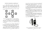
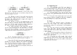
3.3.1. The stress indicator consists of a magnetizing
device 1, an electronic unit 2, and a sensor 3 connected to the
electronic unit via a connector.
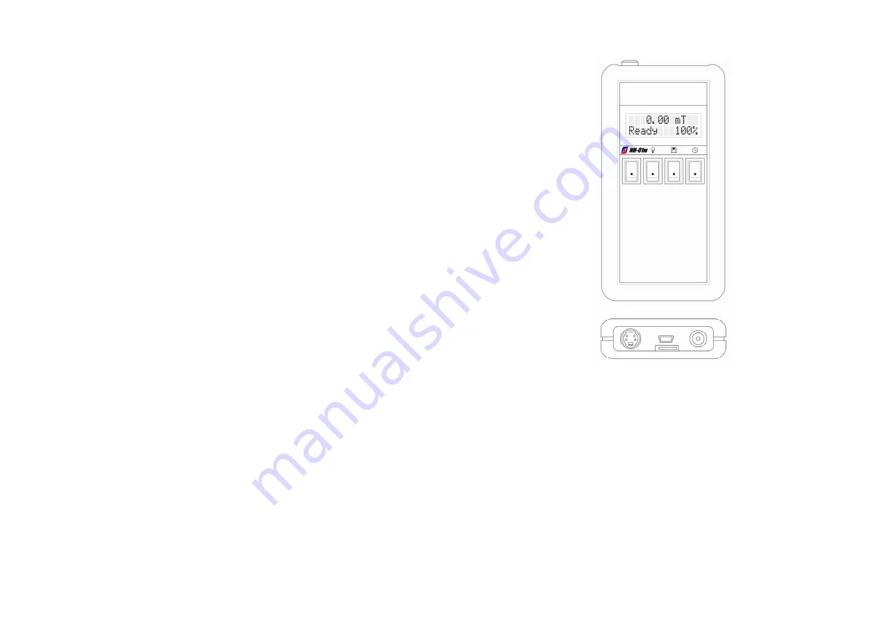
3.3.2. On the front panel of the electronic unit, there is
a digital liquid crystal display 4, a power button 5, a button for
turning on the device's screen backlight 6, a button for
recording the measurement in memory 7, and a button for
displaying the current date and time 8 (Fig.3.3).
3.3.3. The battery cover is located on the back of the
electronic unit housing. To remove the battery from the battery
compartment, press the battery cover slightly and slide it
down.
3.3.4. In the upper part of the electronic unit housing,
there is a panel of connectors (Fig.3.3).
3.3.4.1. Connector 9 is used for connecting to the
electronic unit of the Sensor.
3.3.4.2. Connector 10 is used for placing a memory
card (flash card) in the electronic block.
3.3.4.3. The mini-USB 11 connector is used for
transmitting measured data via a cable to a personal computer
and receiving service information from the computer.
3.3.4.4. Connector 12 is used to connect the charger's
network adapter to the electronic unit for recharging the
battery (battery).
3.4. The purpose of the controls of stress indicator
3.4.1. The liquid crystal display 4 is used to display
information during the operation of the stress indicator.
3.4.2. Button 5 is used to turn on the electric power of
the stress indicator.
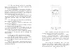
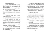
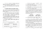
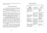
When you turn on button 5 information about the type
of stress indicator appears on its screen for a short time and its
serial number (Fig.3.4 a).
10
Fig.3.3. Location of controls and connectors of the
electronic unit of IN-01m the metal stress indicator
4 – alphanumeric liquid crystal display, 5 – power
button, 6 – screen backlight button, 7 – button to perform
recording measurements in memory, 8 – button for displaying
the date and time, 9 – sensor connector, 10 – memory card
slot, 11 – mini-USB connector, 12 – connector for charger
network adapter.
After setting the measurement mode, the stress
indicator screen displays a digital indication of the output
signal of the sensor (mT or MPa) the battery charge level of
the stress indicator in % , and its ready state (Fig.3.4 b).
4
5 6 7 8
9
10
11
12


