background image

 6 

The Spectra Cabo-10,000 watermaker is designed for use in seagoing vessels or 
platforms.  Feed water must be supplied to the system a minimum of 20 gpm (76lpm) 
at  ≈20psi (1.4 Bar) pressure.   The machine separates the feed water into two 
streams; product and brine.  The brine stream contains the dissolved solids removed 
from the product water.  Brine flow may be as high as 13 gpm (50L/min) and should be 
discharged above the waterline.  The system requires a small amount of back pressure 
on the brine stream so plumb the discharge accordingly.  Long runs in solid tubing will 
require a vacuum break so as to not create any suction at the brine discharge. 

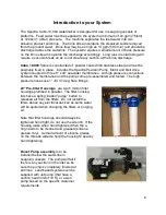
Cabo 10,000 

frame is constructed of  powder coated 304 stainless steel and must be 

positively fixed in place.  includes the Spectra Pearson Pump, Motor and Belt drive 
system coupled to three 8” x 40” seawater membranes.  All high pressure connections 
between the membranes and the pump come pre-assembled and tested.  The high 
pressure hoses use 1” JIC 37 deg. flare fittings.  

20” Pre-filter Housings 

 are two 5 micron filter 

housings plumbed in parallel.  The filter housing 
lids have a spring loaded “purge” button to 
released air from the filters.  Do not install the 
filters above any electrical devices as some water 
will be spilled when changing the filters or purging 
air.  

Note that filter housings should always be 
tightened hand tight, do not use the wrench.  If the 
housing leaks when hand tightened then the o-
ring needs to be cleaned and greased (silicone 
grease only).  A small amount of silicone grease 
on the threads will also help the housing to seal by 
hand tightening. 

Boost Pump assembly 

is to be 

installed below the water line in 
seagoing vessels.  The pump will fail if 
there is any suction on the inlet so be 
sure the pump is completely flooded at 
all times.  Land based systems will be 
supplied with Jet pump (that have a 
suction head limit of 10 ft.) or a well 
pump based on the specific customer 
requirements. 

Introduction to your System 

Summary of Contents for CABO 10,000

Page 1: ...LLC 2220 S McDowell Blvd Petaluma CA 94954 Phone 415 526 2780 Fax 415 526 2787 techsupport spectrawatermakers com www spectrawatermakers com Updated March 2019 CABO 10 000 With SP 20 Pearson Pump Tech...

Page 2: ...2...

Page 3: ...hematic 10 Page Installation Instructions Care and Maintenance Maintenance 14 Long Term Storage 15 Winterizing 16 Membranes 17 Clean in Place Procedures 18 Troubleshooting 19 Operation Initial Start u...

Page 4: ...4...

Page 5: ...a moment to review this manual before operating the machine and if you have any questions Contact techsupport spectrawatermakers com Parts List Any shipping damage must be reported to the carrier wit...

Page 6: ...between the membranes and the pump come pre assembled and tested The high pressure hoses use 1 JIC 37 deg flare fittings 20 Pre filter Housings are two 5 micron filter housings plumbed in parallel The...

Page 7: ...open the electrical box after installation use caution as there is live AC in the box Note For smooth and safe operation always open the pressure relief valve prior to starting or stopping the waterm...

Page 8: ...inst chafing and size all wiring according to industry standards and local regulations There is a 10 ft length of SOJ power cord included but not connected and a strain relief built into box CAUTION U...

Page 9: ...no feed pump on service speed about 1 2 speed or 10 gpm for fresh water flushing cleaning or pickling After the system is purged use the brine discharge valve to restrict the flow so the Brine Dischar...

Page 10: ...o Membranes High Pressure Return Membrane Array Boost Pump Optional Media filter Feed Water Flow Gauge Filter Array Flush Valve Pearson Energy Recovery Pump Pressurized Fresh water from tank Fresh wat...

Page 11: ...re in the run position as seen in the picture at right Brine discharge is connected and there are no restrictions on the line The brine discharge will contain a small amount of propylene glycol potabl...

Page 12: ...w the pump to operate at peak performance 9 Close the pressure relief valve 11 Allow the system to run for an hour or so while you check for leaks Note that knocking in the system indicated either inc...

Page 13: ...ystem is will become important to understand the systems past performance Many troubleshooting questions start with how has the system been running in the past so keeping a log of performance will be...

Page 14: ...will permanently damage the filter housing bowl The Crankcase Change the crankcase oil every 5000 hours or if it begins to darken in color or become milky Milky oil indicates seal failure so replace s...

Page 15: ...lved Warm water will allow the SC 1 to dissolve more quickly Attach the service hoses place the open ends of the hoses in the bucket and turn both the service valves to SERVICE valves in picture shown...

Page 16: ...wn in run position Use the Service toggle switch on the front of the control panel to run the pump Circulate the antifreeze for 20 minutes Turn both the service valves to the off position vertical Lea...

Page 17: ...on There are two types of cleaners acid and alkaline The acid cleaner SC 3 will remove mineral scaling The alkaline cleaner SC 2 is used to remove biological by products oil and dirt particles that ge...

Page 18: ...bucket of the unchlorinated water stir until well dissolved Attach the service hoses place the open ends of the hoses in the bucket and turn both the service valves to SERVICE valves in picture shown...

Page 19: ...Skipping Teeth on Gear End Belt Too Loose Motor Turning Wrong Direction Tighten Belt Run motor in reverse direction by swapping T1 and T2 on VFD Output terminals AC Systems Only Permeate Flow Decreas...

Page 20: ...sure Motor Problem VFD Problem Resolution Check membrane pressure against nominal system parameters Check Supply Pump for proper operation and adequate flow through pre filtration system Test motor re...

Page 21: ...21...

Page 22: ...22 Connector Pin Locations and speed control settings...

Page 23: ...23 Boost Pump Speed control...

Page 24: ...ater Supply Minimum Pressure after filters 10 psi 7 bar Maximum Pressure after filters 20 psi 1 4 bar Flow Rate 20gpm 76 L min Total Dissolved solids 0 45 000 mg L pH range 4 11 Continuous free chlori...

Page 25: ...25...

Reviews: