INSTALLATIONS
10
IB965 User’s Manual
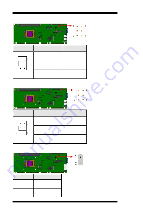
JP1: COM1 RS232 RI/+5V/+12V Power Setting
JP1
Setting
Function
Pin 1-3
Short/Closed
+12V
Pin 3-4
Short/Closed
RI
Pin 3-5
Short/Closed
+5V
JP2: COM2 RS232 RI/+5V/+12V Power Setting
JP2
Setting
Function
Pin 1-3
Short/Closed
+12V
Pin 3-4
Short/Closed
RI
Pin 3-5
Short/Closed
+5V
JP3: Power On Type
JP3
Function
Open
ATX Mode
(Default)
Close
AT Mode
Summary of Contents for IB965F
Page 4: ...iv IB965 User s Manual This page is intentionally left blank ...
Page 9: ...INTRODUCTION IB965 User s Manual 5 Board Dimensions ...
Page 19: ...INSTALLATIONS IB965 User s Manual 15 Connector Locations on IB965F ...
Page 74: ...DRIVER INSTALLATION 70 IB965 User s Manual This page is intentionally left blank ...


