Spectra
GmbH
&
Co.
KG
vertrieb@spectra.de
User
Manual
‐
Spectra
PowerTwin
P
Apollo
Lake
+
standard Displays
Version
1.0
September
2018
49
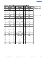
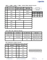
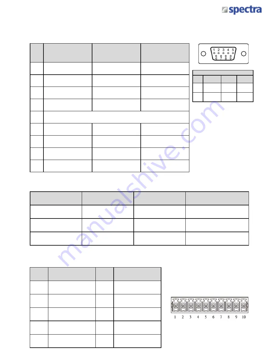
COM1_1 / COM2_1 / COM3_1 / COM4_1 : RS232 / RS422 / RS485 Connector
Connector Type: 9-pin D-Sub
Pin
RS232 Definition
RS422 / 485 Full
Duplex Definition
RS485 Half
Duplex Definition
1
DCD
TX-
DATA1-
2
RXD
TX+
DATA1+
3
TXD
RX+
4
DTR
RX-
5
GND
6
DSR
7
RTS
8
CTS
9
RI
Power over Serial PIN Definitions
Pin
RS232
RS422/
485
RS485
5
GND
GND
GND
9
0/5/12V
0/5/12V
0/5/12V
LAN1 / LAN2: LAN LED Status Definition
Act LED Status
Definition
Link LED Status
Definition
Blinking Yellow
Data Activity
Steady Green
1Gbps Network Link
Off
No Activity
Steady Orange
100Mbps Network Link
Off
10Mbps Network Link
DIO1: Digital Input / Output Connector
Connector Type: Terminal Block 1X10 10-pin, 3.5mm pitch
Pin
Definition
Pin
Definition
1
XCOM+
6
DO1
2
DI1
7
DO2
3
DI2
8
DO3
4
DI3
9
DO4
5
DI4
10
XCOM-
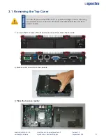
Summary of Contents for PowerTwin PS12-E3950C9
Page 12: ...Product Introductions Chapter 1...
Page 28: ...System Pin Definitions and Settings Chapter 2...
Page 38: ...System Setup Chapter 3...
Page 56: ...BIOS Setup Chapter 4...
Page 99: ...Product Introductions Chapter 1...
Page 129: ...System Pin Definitions and Settings Chapter 2...
Page 139: ...System Setup Chapter 3...
Page 157: ...BIOS Setup Chapter 4...

